
Smart Irrigation System with ESP32 and Blynk App Integration
View and Edit Project In Cirkit Designer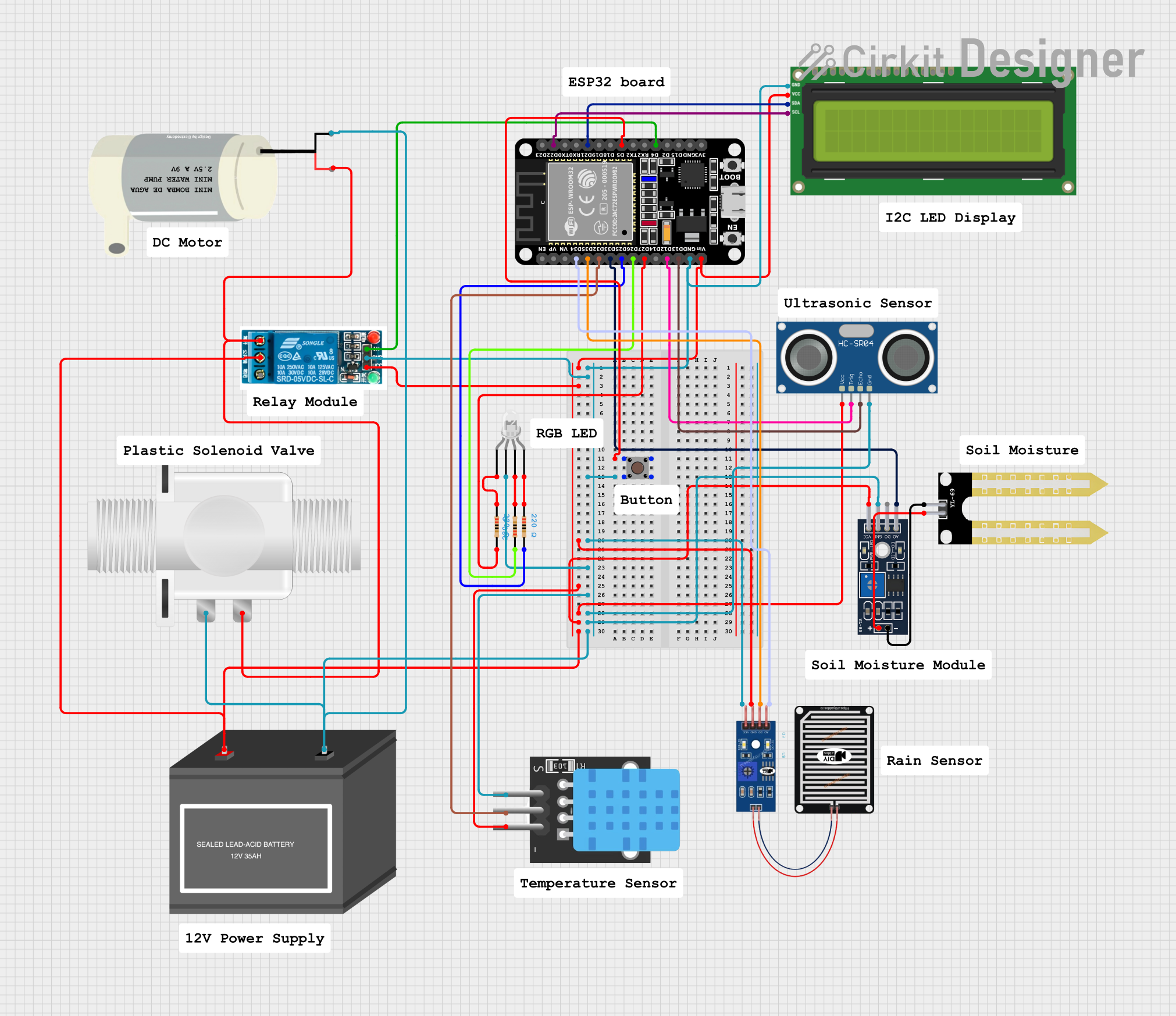
Circuit Documentation
Summary
This circuit is designed to create a smart irrigation system with Blynk integration. It features an ESP32 microcontroller that interfaces with various sensors and actuators, including a rain sensor, temperature sensor, ultrasonic sensor, and a relay module to control a water pump and a solenoid valve. The system's status is displayed on an I2C LCD screen, and the ESP32 allows for remote monitoring and control via the Blynk platform.
Component List
5v Relay
- Description: A relay is an electrically operated switch that allows you to control a high-power circuit with a low-power signal.
- Pins: Normally Open, Common terminal, Normally Closed, In, GND, VCC
I2C LCD 16x2 Screen
- Description: A 16x2 character LCD display that uses the I2C communication protocol for displaying text and numbers.
- Pins: SCL, SDA, VCC (5V), GND, VDD, VO, RS, RW, E, D0, D1, D2, D3, D4, D5, D6, D7, BLA, BLK
YL-83 Module LM393
- Description: A raindrop sensor module that can detect rain and measure rain intensity.
- Pins: A0, D0, GND, VCC, -, +
Mini Water Pump
- Description: A small pump used for moving water, typically used in small-scale irrigation or water feature applications.
- Pins: VCC, GND
LED: Four Pin (Common Cathode)
- Description: A four-pin LED with a common cathode and separate anodes for red, green, and blue colors.
- Pins: red anode, common cathode, green anode, blue anode
Resistor (220 Ohms)
- Description: A passive two-terminal electrical component that implements electrical resistance as a circuit element.
- Pins: pin1, pin2
- Properties: Resistance: 220 Ohms
Pushbutton
- Description: A simple switch mechanism for controlling some aspect of a machine or a process.
- Pins: Pin 3 (out), Pin 4 (out), Pin 1 (in), Pin 2 (in)
HC-SR04 Ultrasonic Sensor
- Description: A sensor that measures distance by emitting ultrasonic waves and timing how long it takes for the echoes to return.
- Pins: VCC, TRIG, ECHO, GND
ESP32 (30 pin)
- Description: A microcontroller with Wi-Fi and Bluetooth capabilities, suitable for a wide variety of applications.
- Pins: EN, VP, VN, D34, D35, D32, D33, D25, D26, D27, D14, D12, D13, GND, Vin, D23, D22, TX0, RX0, D21, D19, D18, D5, TX2, RX2, D4, D2, D15, 3V3
YL-69 Sonda
- Description: A soil moisture sensor probe that measures the volumetric content of water in the soil.
- Pins: +, -
Plastic Solenoid Valve
- Description: An electrically controlled valve used for controlling the flow of liquids.
- Pins: pin1, pin2
RAIN SENSOR
- Description: A sensor that detects rain and provides both analog and digital outputs.
- Pins: AO, DO, GRD, VCC
TEMP
- Description: A temperature sensor that provides digital output.
- Pins: 5V, D3, GND
12V Battery (mini)
- Description: A small 12V battery used to power the circuit.
- Pins: -, +
Wiring Details
5v Relay
- In: Connected to ESP32 D4
- GND: Connected to common ground
- VCC: Connected to ESP32 Vin
- Common terminal: Connected to 12V Battery (+)
- Normally Open: Connected to Mini Water Pump VCC and Plastic Solenoid Valve pin2
I2C LCD 16x2 Screen
- SCL: Connected to ESP32 D22
- SDA: Connected to ESP32 D21
- VCC (5V): Connected to ESP32 Vin
- GND: Connected to common ground
YL-83 Module LM393
- A0: Connected to ESP32 D33
- D0: Not connected
- GND: Connected to common ground
- VCC: Connected to ESP32 Vin
- -: Connected to YL-69 Sonda -
- +: Connected to YL-69 Sonda +
Mini Water Pump
- VCC: Connected to 5v Relay Normally Open
- GND: Connected to common ground
LED: Four Pin (Common Cathode)
- red anode: Connected to Resistor (220 Ohms) pin1
- common cathode: Connected to common ground
- green anode: Connected to Resistor (220 Ohms) pin2
- blue anode: Connected to Resistor (220 Ohms) pin1
Resistor (220 Ohms)
- pin1: Connected to ESP32 D26, D27, and D25 for red, green, and blue anodes of LED respectively
- pin2: Connected to LED red anode, green anode, and blue anode respectively
Pushbutton
- Pin 1 (in) and Pin 2 (in): Connected to ESP32 D5
- Pin 3 (out) and Pin 4 (out): Connected to common ground
HC-SR04 Ultrasonic Sensor
- VCC: Connected to ESP32 Vin
- TRIG: Connected to ESP32 D12
- ECHO: Connected to ESP32 D13
- GND: Connected to common ground
ESP32 (30 pin)
- D5: Connected to Pushbutton Pin 1 (in) and Pin 2 (in)
- GND: Connected to common ground
- Vin: Connected to I2C LCD VCC (5V), YL-83 Module VCC, HC-SR04 VCC, and 5v Relay VCC
- D4: Connected to 5v Relay In
- D22: Connected to I2C LCD SCL
- D21: Connected to I2C LCD SDA
- D33: Connected to YL-83 Module A0
- D12: Connected to HC-SR04 TRIG
- D13: Connected to HC-SR04 ECHO
- D25, D26, D27: Connected to Resistor (220 Ohms) pin1 for controlling the LED
YL-69 Sonda
- +: Connected to YL-83 Module +
- -: Connected to YL-83 Module -
Plastic Solenoid Valve
- pin1: Connected to common ground
- pin2: Connected to Mini Water Pump VCC and 5v Relay Normally Open
RAIN SENSOR
- AO: Connected to ESP32 D34
- DO: Connected to ESP32 D35
- GRD: Connected to common ground
- VCC: Connected to ESP32 Vin
TEMP
- 5V: Connected to common ground
- D3: Connected to ESP32 D32
- GND: Connected to common ground
12V Battery (mini)
- -: Connected to common ground
- +: Connected to 5v Relay Common terminal
Documented Code
ESP32 Microcontroller Code (sketch.ino)
void setup() {
  // put your setup code here, to run once:

}

void loop() {
  // put your main code here, to run repeatedly:

}
Smart Irrigation System Code (sketch.ino)
/*
 * Smart Irrigation System with Blynk Integration
 * This code reads sensor data from the YL-83 Module LM393 and controls
 * a relay to operate a solenoid valve and a water pump. The water level
 * status is displayed on an I2C LCD and can be monitored/controlled via Blynk.
 */

#include <Wire.h>
#include <LiquidCrystal_I2C.h>
#include <BlynkSimpleEsp32.h>

// Blynk Auth Token
char auth[] = "YourAuthToken";

// WiFi credentials
char ssid[] = "YourNetworkName";
char pass[] = "YourPassword";

// Pin definitions
#define RELAY_PIN 4
#define WATER_LEVEL_PIN 33
#define TRIG_PIN 12
#define ECHO_PIN 13
#define RED_LED_PIN 27
#define GREEN_LED_PIN 26
#define BLUE_LED_PIN 25

// I2C LCD address and dimensions
LiquidCrystal_I2C lcd(0x27, 16, 2);

void setup() {
  // Initialize serial communication
  Serial.begin(115200);

  // Initialize the LCD
  lcd.begin();
  lcd.backlight();

  // Initialize pin modes
  pinMode(RELAY_PIN, OUTPUT);
  pinMode(WATER_LEVEL_PIN, INPUT);
  pinMode(TRIG_PIN, OUTPUT);
  pinMode(ECHO_PIN, INPUT);
  pinMode(RED_LED_PIN, OUTPUT);
  pinMode(GREEN_LED_PIN, OUTPUT);
  pinMode(BLUE_LED_PIN, OUTPUT);

  // Initial state
  digitalWrite(RELAY_PIN, LOW);
  lcd.setCursor(0, 0);
  lcd.print("Smart Irrigation");