
Arduino UNO Controlled Robot with FlySky FS-IA6 and L298N Motor Driver
View and Edit Project In Cirkit Designer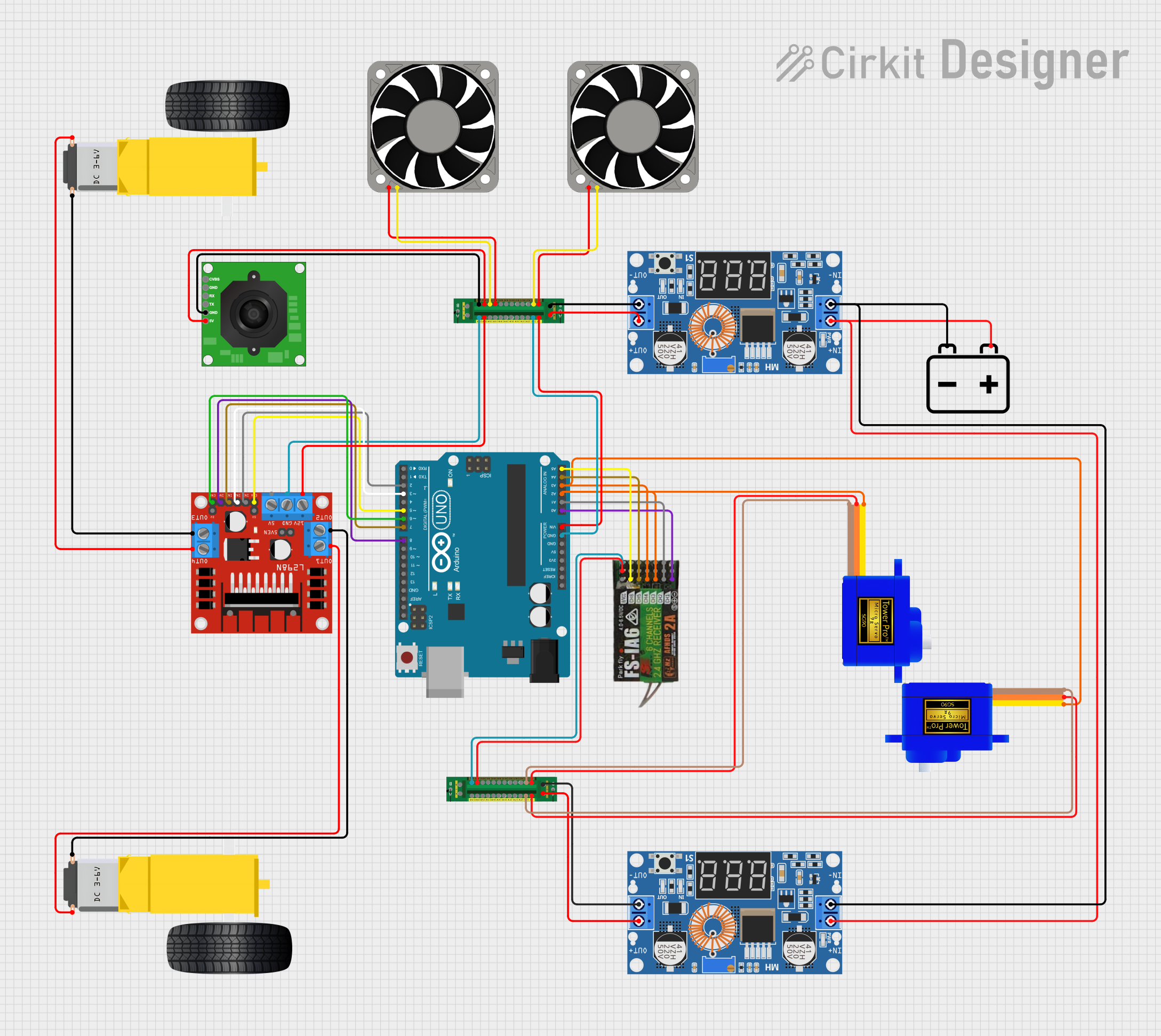
Circuit Documentation
Summary
This document provides a detailed overview of a robot control circuit. The circuit includes various components such as an Arduino UNO, servomotors, DC motors, a motor driver, a power distribution board, a FlySky FS-IA6 receiver, and a TTL Serial JPEG Camera. The robot is controlled using a FlySky FS-IA6 controller, with the right joystick managing the DC motors for movement and the left joystick controlling the servos for pan and tilt of an FPV camera.
Component List
Arduino UNO
- Description: Microcontroller board based on the ATmega328P.
- Pins: UNUSED, IOREF, Reset, 3.3V, 5V, GND, Vin, A0, A1, A2, A3, A4, A5, SCL, SDA, AREF, D13, D12, D11, D10, D9, D8, D7, D6, D5, D4, D3, D2, D1, D0
TTL Serial JPEG Camera
- Description: Camera module with TTL serial interface.
- Pins: GND, RX, TX, CVBS, 5V
Servomotor SG90
- Description: Small servomotor for precise control.
- Pins: SIG, VCC, GND
Gearmotor DC Wheels left
- Description: DC motor for left wheel.
- Pins: PIN1, PIN2
Gearmotor DC Wheels Right
- Description: DC motor for right wheel.
- Pins: PIN1, PIN2
Power Distribution Board
- Description: Board for distributing power to various components.
- Pins: Output 1+, Input +, Input -, Output 2+, Output 2-, Output 3+, Output 4+, Output 5+, Output 1-, Output 4-, Output 3-, Output 5-, Output 6+, Output 6-, Output 7+, Output 7-, Output 8+, Output 8-, Output 9+, Output 9-, Output 10+, Output 10-, Output 11+, Output 11-, Output 12+, Output 12-, Output +, Output -
L298N DC motor driver
- Description: Dual H-Bridge motor driver for controlling DC motors.
- Pins: OUT1, OUT2, 12V, GND, 5V, OUT3, OUT4, 5V-ENA-JMP-I, 5V-ENA-JMP-O, +5V-J1, +5V-J2, ENA, IN1, IN2, IN3, IN4, ENB
XL4015 5A DC Buck Step-down
- Description: DC-DC buck converter for voltage regulation.
- Pins: Output +, Output -, Input +, Input -
40 Fan 12v
- Description: 12V cooling fan.
- Pins: +12V, -12V
12v Battery
- Description: Power source for the circuit.
- Pins: -, +
FLYSKY FS-IA6
- Description: 6-channel receiver for FlySky transmitters.
- Pins: CH1, 5V, GND, CH2, CH3, CH4, CH5, CH6, VCC
Wiring Details
Arduino UNO
- GND connected to Power Distribution Board (Output 7-)
- Vin connected to Power Distribution Board (Output 7+)
- A0 connected to FLYSKY FS-IA6 (CH1)
- A1 connected to FLYSKY FS-IA6 (CH2)
- A2 connected to FLYSKY FS-IA6 (CH3) and Servomotor SG90 (SIG)
- A3 connected to FLYSKY FS-IA6 (CH4) and Servomotor SG90 (SIG)
- A4 connected to FLYSKY FS-IA6 (CH5)
- A5 connected to FLYSKY FS-IA6 (CH6)
- D8 connected to L298N DC motor driver (IN4)
- D7 connected to L298N DC motor driver (IN3)
- D6 connected to L298N DC motor driver (ENB)
- D5 connected to L298N DC motor driver (ENA)
- D3 connected to L298N DC motor driver (IN2)
- D2 connected to L298N DC motor driver (IN1)
TTL Serial JPEG Camera
- GND connected to Power Distribution Board (Output 6-)
- 5V connected to Power Distribution Board (Output 6+)
Servomotor SG90
- SIG connected to Arduino UNO (A2)
- VCC connected to Power Distribution Board (Output 1+)
- GND connected to Power Distribution Board (Output 1-)
Servomotor SG90
- SIG connected to Arduino UNO (A3)
- VCC connected to Power Distribution Board (Output 7+)
- GND connected to Power Distribution Board (Output 7-)
Gearmotor DC Wheels left
- PIN1 connected to L298N DC motor driver (OUT2)
- PIN2 connected to L298N DC motor driver (OUT1)
Gearmotor DC Wheels Right
- PIN1 connected to L298N DC motor driver (OUT4)
- PIN2 connected to L298N DC motor driver (OUT3)
Power Distribution Board
- Output 7- connected to Arduino UNO (GND)
- Output 7+ connected to Arduino UNO (Vin)
- Output 1+ connected to Servomotor SG90 (VCC)
- Output 1- connected to Servomotor SG90 (GND)
- Output 7+ connected to Servomotor SG90 (VCC)
- Output 7- connected to Servomotor SG90 (GND)
- Output 6+ connected to FLYSKY FS-IA6 (5V)
- Output 6- connected to FLYSKY FS-IA6 (GND)
- Output 6- connected to TTL Serial JPEG Camera (GND)
- Output 6+ connected to TTL Serial JPEG Camera (5V)
- Output 12+ connected to L298N DC motor driver (12V)
- Output 12- connected to L298N DC motor driver (GND)
- Input + connected to XL4015 5A DC Buck Step-down (Output +)
- Input - connected to XL4015 5A DC Buck Step-down (Output -)
L298N DC motor driver
- IN4 connected to Arduino UNO (D8)
- IN3 connected to Arduino UNO (D7)
- ENB connected to Arduino UNO (D6)
- ENA connected to Arduino UNO (D5)
- IN2 connected to Arduino UNO (D3)
- IN1 connected to Arduino UNO (D2)
- OUT2 connected to Gearmotor DC Wheels left (PIN1)
- OUT1 connected to Gearmotor DC Wheels left (PIN2)
- OUT4 connected to Gearmotor DC Wheels Right (PIN1)
- OUT3 connected to Gearmotor DC Wheels Right (PIN2)
- 12V connected to Power Distribution Board (Output 12+)
- GND connected to Power Distribution Board (Output 12-)
XL4015 5A DC Buck Step-down
- Output + connected to Power Distribution Board (Input +)
- Output - connected to Power Distribution Board (Input -)
- Input + connected to 12v Battery (+)
- Input - connected to 12v Battery (-)
40 Fan 12v
- +12V connected to Power Distribution Board (Output 1+)
- -12V connected to Power Distribution Board (Output 1-)
40 Fan 12v
- +12V connected to Power Distribution Board (Output 5+)
- -12V connected to Power Distribution Board (Output 5-)
12v Battery
- + connected to XL4015 5A DC Buck Step-down (Input +)
- - connected to **XL4015 5A DC Buck Step