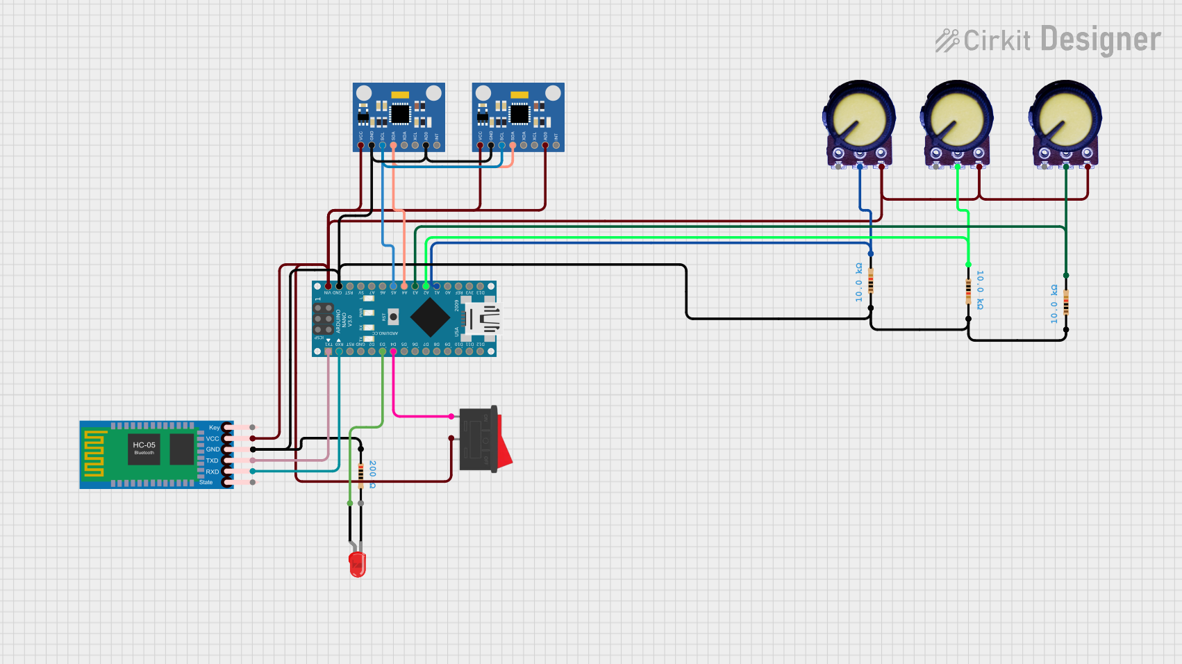
Arduino Nano and MPU6050 Based Gesture-Controlled Robotic Arm with Bluetooth Connectivity

Circuit Documentation
Summary
The circuit in question appears to be a complex system involving multiple MPU6050 Accelerometer + Gyroscope modules, Arduino Nano microcontrollers, LEDs, potentiometers, resistors, an HC-05 Bluetooth module, and a rocker switch. The primary function of this circuit is likely to capture motion data from the MPU6050 sensors and use this data to control a robotic arm or similar device via Bluetooth communication. The potentiometers may be used for manual control or calibration, and the LEDs serve as indicators. The Arduino Nanos are programmed to process sensor data and handle communication with the Bluetooth module.
Component List
Microcontrollers
- Arduino Nano: A compact microcontroller board based on the ATmega328P, featuring digital and analog I/O pins.
Sensors
- MPU6050 Accelerometer + Gyroscope (Wokwi Compatible): A motion tracking device that combines a 3-axis gyroscope and a 3-axis accelerometer.
Communication Modules
- HC-05 Bluetooth Module: A wireless communication module that allows for Bluetooth connectivity.
Indicators
- LED: Two Pin (red): A simple red light-emitting diode used for indication purposes.
Passive Components
- Potentiometer: A three-terminal resistor with an adjustable voltage divider.
- Resistor: A passive two-terminal electrical component that implements electrical resistance as a circuit element.
Switches
- Rocker Switch: An on-off switch that rocks (rather than trips) when pressed.
Wiring Details
Arduino Nano
- Digital Pins: Used for various control signals and communication with other devices.
- Analog Pins (A0-A7): Used to read analog values from sensors like potentiometers.
- Power Pins (VIN, 3V3, 5V, GND): Provide power to the board and connected components.
MPU6050 Accelerometer + Gyroscope
- SDA/SCL: Connected to the I2C data and clock lines for communication with the Arduino Nano.
- INT: Interrupt pin, typically used to alert the microcontroller of a motion event.
- AD0: Address selection pin for I2C communication.
- VCC/GND: Power supply pins.
HC-05 Bluetooth Module
- TXD/RXD: Transmit and receive pins for serial communication with the Arduino Nano.
- VCC/GND: Power supply pins.
- Key/State: Pins for module configuration and status indication.
LED: Two Pin (red)
- Anode/Cathode: Connected to a digital pin on the Arduino Nano and ground through a current-limiting resistor.
Potentiometer
- VCC/Output/GND: Power supply pins and the variable output connected to an analog pin on the Arduino Nano.
Resistor
- Pin1/Pin2: Connected in series or parallel configurations for current limiting or voltage division.
Rocker Switch
- Pin1/Pin2: Used to control the power supply to a section of the circuit.
Documented Code
Arduino Nano Code
#include<Wire.h>

//Create thumb Sensors
int pinkie = 0; //Pinkie thumb
int finger = 0; //finger thumb
int thumb = 0; //Index thumb

int pinkie_Data = A1;
int finger_Data = A2;
int thumb_Data = A3;

// MPU6050 Addresses
const int MPU2 = 0x69, MPU1 = 0x68;

//First MPU6050
int16_t AcX1, AcY1, AcZ1, Tmp1, GyX1, GyY1, GyZ1;
int minVal = 265;
int maxVal = 402;
double x;
double y;
double z;

//Second MPU6050
int16_t AcX2, AcY2, AcZ2, Tmp2, GyX2, GyY2, GyZ2;
int minVal2 = 265;
int maxVal2 = 402;
double x2;
double y2;
double z2;

//Autotune flex parameter
// For Debug Mode. Check the upper and lower limit of the flex sensors
// 3 Flex sensors used. Thumb, Middle, Pinkie
int thumb_high = 0;
int thumb_low = 0;
int finger_high = 0;
int finger_low = 0;
int pinkie_high = 0;
int pinkie_low = 0;

//Stop Calibrating the Flex Sensor when complete
bool bool_calibrate = false;

//How often to send values to the Robotic Arm
int response_time = 100;

void setup() {
  pinMode(3, OUTPUT);
  Wire.begin();
  // Initialize MPU6050 devices
  initMPU(MPU1);
  initMPU(MPU2);
  Serial.begin(4800);
  delay(1000);
}

void loop() {
  // Use basic LED as visual indicator if value being sent
  digitalWrite(3, HIGH);

  // Read values from both MPU6050 sensors
  GetMpuValue(MPU1, AcX1, AcY1, AcZ1, Tmp1, GyX1, GyY1, GyZ1, x, y, z);
  GetMpuValue(MPU2, AcX2, AcY2, AcZ2, Tmp2, GyX2, GyY2, GyZ2, x2, y2, z2);

  // Process sensor data and send commands
  processSensorData();

  // Read and process flex sensor data
  readFlexSensors();

  // Calibrate flex sensors if needed
  if (!bool_calibrate) {
    calibrateFlexSensors();
  }

  delay(response_time);
}

// Function definitions for initMPU, GetMpuValue, processSensorData, readFlexSensors, calibrateFlexSensors, etc.
// These functions encapsulate the functionality described in the loop and setup functions.
Note: The code above is a simplified and structured representation of the provided code snippets. The actual implementation of the functions initMPU, GetMpuValue, processSensorData, readFlexSensors, and calibrateFlexSensors would be necessary to complete the code documentation. The code provided in the input is for a single Arduino Nano, but the circuit includes multiple Arduino Nanos and MPU6050 sensors, suggesting that similar code may be running on each microcontroller with potential variations for different tasks or sensor addresses.