
Solar-Powered Battery Monitoring System with Arduino Nano and OLED Display
View and Edit Project In Cirkit Designer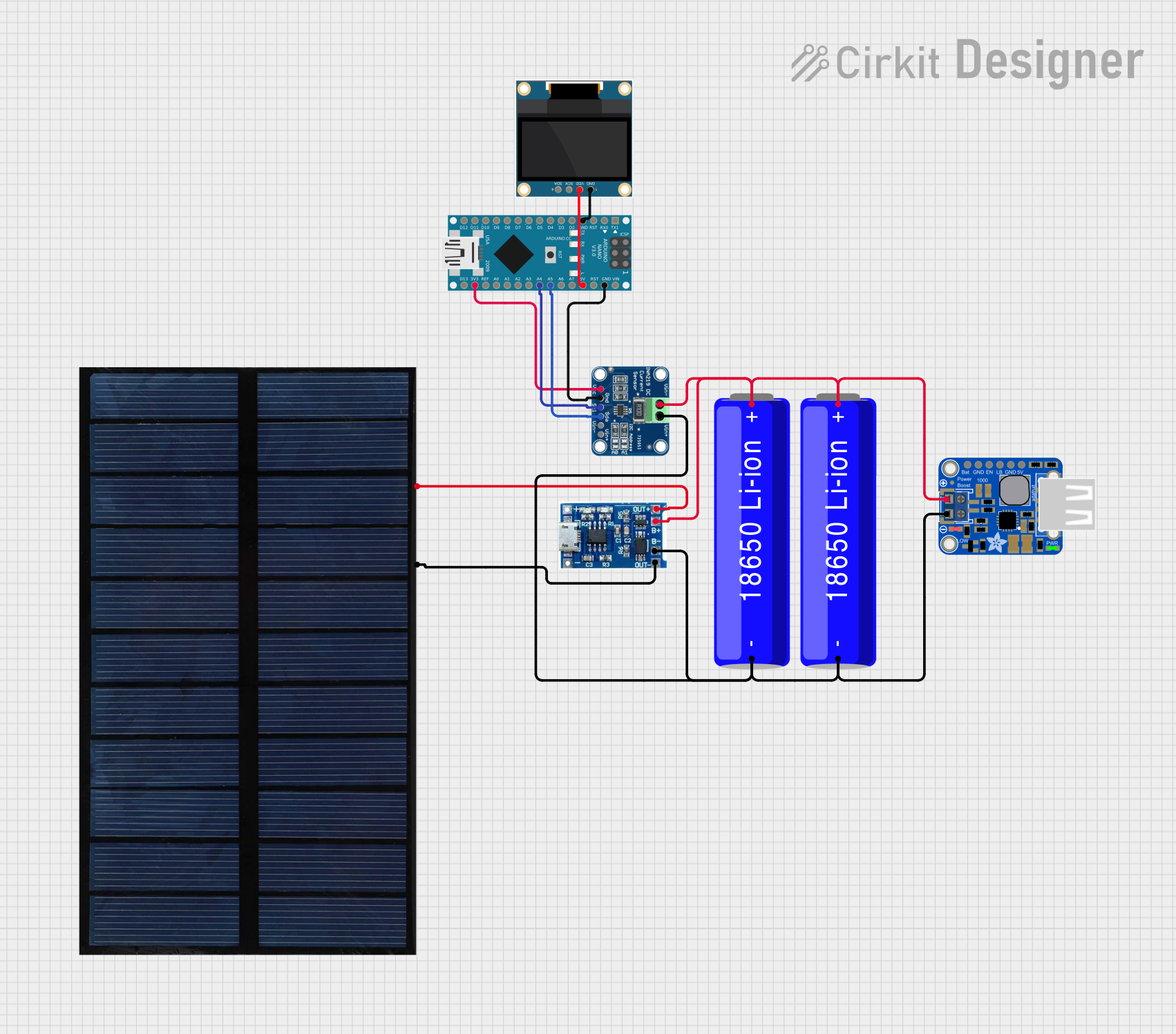
Circuit Documentation
Summary
This circuit is designed to manage and monitor the charging of a 18650 Li-ion battery using a solar cell. The circuit includes a LiPo battery charger module, a PowerBoost 1000 Basic Terminal USB for voltage regulation, an INA219 sensor for current and voltage measurement, an Arduino Nano for control and data processing, and a 0.96" OLED display for visual feedback.
Component List
Solar Cell
- Description: Converts sunlight into electrical energy.
- Pins: +, -
LiPo Battery Charger Module
- Description: Manages the charging of the Li-ion battery.
- Pins: B-, B+, OUT-, OUT+
PowerBoost 1000 Basic Terminal USB
- Description: Boosts the battery voltage to a stable 5V output.
- Pins: VBAT, GND, ENABLE, LBO, 5.0V
18650 Li-ion Battery
- Description: Rechargeable lithium-ion battery.
- Pins: +, -
INA219
- Description: Current and voltage sensor.
- Pins: VCC, GND, SCL, SDA, VIN -, VIN +
Arduino Nano
- Description: Microcontroller for control and data processing.
- Pins: D1/TX, D0/RX, RESET, GND, D2, D3, D4, D5, D6, D7, D8, D9, D10, D11/MOSI, D12/MISO, VIN, 5V, A7, A6, A5, A4, A3, A2, A1, A0, AREF, 3V3, D13/SCK
0.96" OLED
- Description: Display for visual feedback.
- Pins: GND, VDD, SCK, SDA
Wiring Details
Solar Cell
- + connected to OUT+ of the LiPo Battery Charger Module
- - connected to OUT- of the LiPo Battery Charger Module
LiPo Battery Charger Module
- B- connected to - of both 18650 Li-ion Batteries and GND of the PowerBoost 1000 Basic Terminal USB
- B+ connected to + of both 18650 Li-ion Batteries and VBAT of the PowerBoost 1000 Basic Terminal USB
- OUT- connected to - of the Solar Cell
- OUT+ connected to + of the Solar Cell
PowerBoost 1000 Basic Terminal USB
- GND connected to B- of the LiPo Battery Charger Module and - of both 18650 Li-ion Batteries
- VBAT connected to B+ of the LiPo Battery Charger Module and + of both 18650 Li-ion Batteries
18650 Li-ion Battery
- - connected to B- of the LiPo Battery Charger Module and GND of the PowerBoost 1000 Basic Terminal USB
- + connected to B+ of the LiPo Battery Charger Module and VBAT of the PowerBoost 1000 Basic Terminal USB
INA219
- VCC connected to 3V3 of the Arduino Nano
- GND connected to GND of the Arduino Nano
- SCL connected to A4 of the Arduino Nano
- SDA connected to A5 of the Arduino Nano
- VIN - connected to + of both 18650 Li-ion Batteries
- VIN + connected to - of both 18650 Li-ion Batteries
Arduino Nano
- 3V3 connected to VCC of the INA219
- GND connected to GND of the INA219 and GND of the 0.96" OLED
- A4 connected to SCL of the INA219
- A5 connected to SDA of the INA219
- 5V connected to VDD of the 0.96" OLED
0.96" OLED
- GND connected to GND of the Arduino Nano
- VDD connected to 5V of the Arduino Nano
Code Documentation
#include <Wire.h>
#include <LiquidCrystal_I2C.h>
#include <INA219.h>

// Initialize with default I2C address (0x40)
INA219 ina219(0x40);

LiquidCrystal_I2C lcd(0x27, 16, 2);

// Battery specifications
const float BATTERY_CAPACITY = 2000.0;  // in mAh
const float FULL_VOLTAGE = 4.2;
const float EMPTY_VOLTAGE = 3.2;

void setup() {
  Serial.begin(9600);
  Wire.begin();

  if (!ina219.begin()) {
    Serial.println("Failed to find INA219 chip");
    while (1) { delay(10); }
  }

  lcd.init();
  lcd.backlight();
}

void loop() {
  float voltage = ina219.getBusVoltage_mV();
  float current = ina219.getCurrent_mA();

  float batteryPercentage = map(voltage * 100,
                               EMPTY_VOLTAGE * 100,
                               FULL_VOLTAGE * 100,
                               0,
                               100);
  batteryPercentage = constrain(batteryPercentage, 0, 100);

  float chargingRate = (current > 0) ? current : 0;

  lcd.clear();
  lcd.setCursor(0, 0);
  lcd.print("Batt: ");
  lcd.print(batteryPercentage, 1);
  lcd.print("%");

  lcd.setCursor(0, 1);
  lcd.print("Chrg: ");
  lcd.print(chargingRate, 1);
  lcd.print("mA");

  Serial.print("Battery: ");
  Serial.print(batteryPercentage);
  Serial.print("% | Charging Rate: ");
  Serial.print(chargingRate);
  Serial.println("mA");

  delay(1000);
}
This code initializes the INA219 sensor and the OLED display, reads the battery voltage and current, calculates the battery percentage and charging rate, and displays this information on the OLED display and the serial monitor.