Arduino UNO-Based Pushbutton LED Control System
Circuit Documentation
Summary
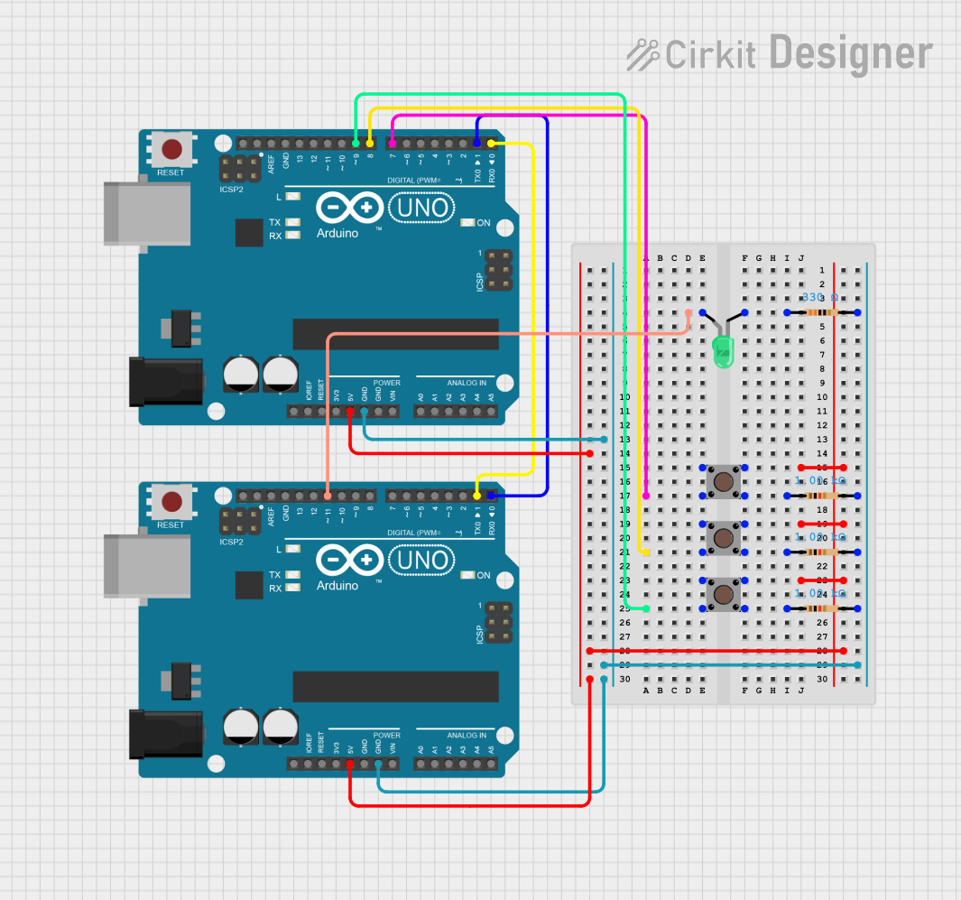
The circuit in question appears to be a simple microcontroller-based system utilizing two Arduino UNO boards. The circuit includes pushbuttons and resistors, as well as a single LED. The pushbuttons are likely used as input devices to trigger certain actions on the Arduino boards, while the LED serves as an output indicator. The resistors are used to limit current to the LED and to provide pull-up or pull-down resistances for the pushbuttons. The Arduinos are interconnected via their serial pins (D0 and D1), allowing them to communicate with each other.
Component List
Microcontrollers
- Arduino UNO: A microcontroller board based on the ATmega328P. It has 14 digital input/output pins, 6 analog inputs, a 16 MHz quartz crystal, a USB connection, a power jack, an ICSP header, and a reset button.
Input Devices
- Pushbutton: A simple switch mechanism for controlling some aspect of a machine or a process. Buttons are typically made out of hard material, usually plastic or metal.
Output Devices
- LED (Green): A light-emitting diode that emits green light when a voltage is applied to its anode and cathode.
Resistors
- 1k Ohm Resistor: A resistor with a resistance of 1000 Ohms, commonly used for current limiting or as a pull-up/pull-down resistor.
- 330 Ohm Resistor: A resistor with a resistance of 330 Ohms, typically used for current limiting for LEDs to protect them from burning out.
Wiring Details
Arduino UNO
- Digital Pin D11: Connected to the anode of the green LED.
- Ground (GND): Connected to the ground pins of all resistors and serves as a common ground with the other Arduino UNO.
- 5V Pin: Supplies power to the pushbuttons.
- Digital Pins D7, D8, D9: Connected to the output pins of the pushbuttons.
- Serial Pins (D0, D1): Interconnected between the two Arduino UNO boards for serial communication.
Pushbuttons
- Pin 1 (in): Connected to the 5V supply from the Arduino UNO.
- Pin 4 (out): Connected to digital pins D7, D8, and D9 on the Arduino UNO.
- Pin 3 (out): Connected to one end of the 1k Ohm resistors.
Resistors
- 1k Ohm Resistors: One end connected to the output of the pushbuttons, the other end connected to the ground (GND).
- 330 Ohm Resistor: One end connected to the cathode of the green LED, the other end connected to the ground (GND).
LED (Green)
- Anode: Connected to digital pin D11 on the Arduino UNO.
- Cathode: Connected to one end of the 330 Ohm resistor.
Documented Code
Arduino UNO (First Board)
void setup() {
  // put your setup code here, to run once:

}

void loop() {
  // put your main code here, to run repeatedly:

}
Arduino UNO (Second Board)
void setup() {
  // put your setup code here, to run once:

}

void loop() {
  // put your main code here, to run repeatedly:

}
Note: The provided code for both Arduino UNO boards is a template with empty setup and loop functions. The actual functionality needs to be implemented according to the requirements of the circuit's application.