Solar-Powered Battery Backup System with Multiple 120V Outlets
Solar Power System Circuit Documentation
Summary
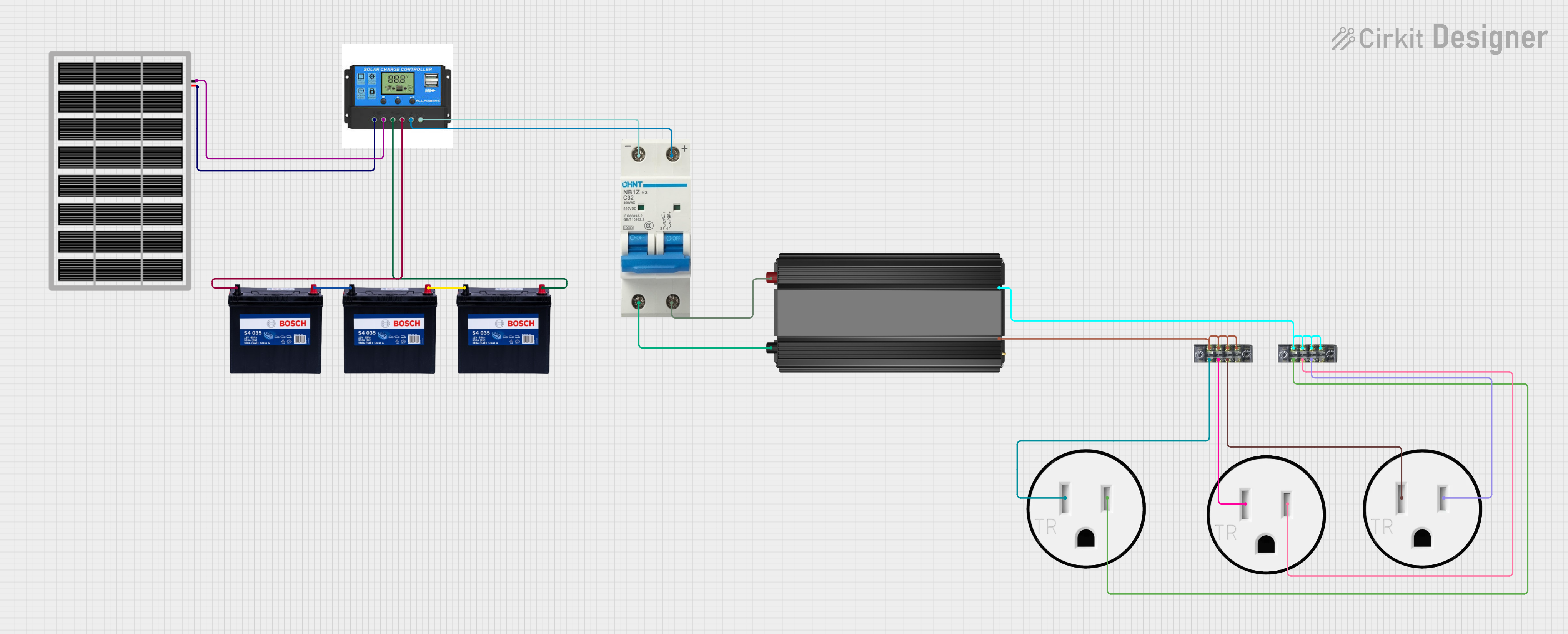
This document provides a detailed overview of a solar power system circuit designed to harness solar energy through a solar panel, manage power flow via a charge controller, store energy in batteries, convert DC to AC power using an inverter, and distribute the power through multiple 120V outlets. The system includes safety features such as a circuit breaker to protect against overcurrent conditions.
Component List
Charge Controller
- Description: Manages the power flow from the solar panel to the battery and the load.
- Pins: Solar Positive, Solar Negative, Battery Positive, Battery Negative, Load Positive, Load Negative
Solar Panel
- Description: Converts sunlight into electrical energy.
- Pins: gnd (Ground), vcc (Voltage)
12V 200Ah Battery
- Description: Stores electrical energy for later use.
- Pins: GND (Ground), 12V (Voltage)
Power Inverter
- Description: Converts DC power from the battery to AC power for household appliances.
- Pins: -, + (DC Input)
Circuit Breaker
- Description: Provides overcurrent protection for the system.
- Pins: -, + (DC Input/Output)
120V Outlet
- Description: Provides an interface for connecting AC-powered devices to the system.
- Pins: AC Neutral, AC Hot
Terminal Block (04-01)
- Description: Facilitates the connection and distribution of wiring.
- Pins: 1, 2, 3, 4, 5, 6, 7, 8
Wiring Details
Charge Controller
- Solar Positive connected to Solar Panel vcc
- Solar Negative connected to Solar Panel gnd
- Battery Positive connected to 12V 200Ah Battery 12V
- Battery Negative connected to 12V 200Ah Battery GND
- Load Positive connected to Circuit Breaker +
- Load Negative connected to Circuit Breaker -
Solar Panel
- vcc connected to Charge Controller Solar Positive
- gnd connected to Charge Controller Solar Negative
12V 200Ah Battery
- 12V connected to Charge Controller Battery Positive
- GND connected to Charge Controller Battery Negative
- Batteries are connected in parallel (12V to GND)
Power Inverter
- connected to Circuit Breaker +
- connected to Circuit Breaker -
Circuit Breaker
- connected to Charge Controller Load Positive and Power Inverter +
- connected to Charge Controller Load Negative and Power Inverter -
120V Outlet
- AC Neutral connected to Terminal Block 6
- AC Hot connected to Terminal Block 2 or 4
Terminal Block (04-01)
- Pins 1, 3, 5, 7 connected to Power Inverter +
- Pins 2, 4, 6, 8 connected to 120V Outlet AC Hot or AC Neutral
Code Documentation
No microcontroller code is provided for this circuit. The system operates without the need for embedded code, relying on the inherent functionality of the components and their physical connections.
This document provides a foundational understanding of the solar power system circuit. For further details or modifications, additional schematics and technical specifications may be required.