
Arduino UNO-Based Bluetooth-Controlled Robotic System with Joystick and Ultrasonic Sensor
View and Edit Project In Cirkit Designer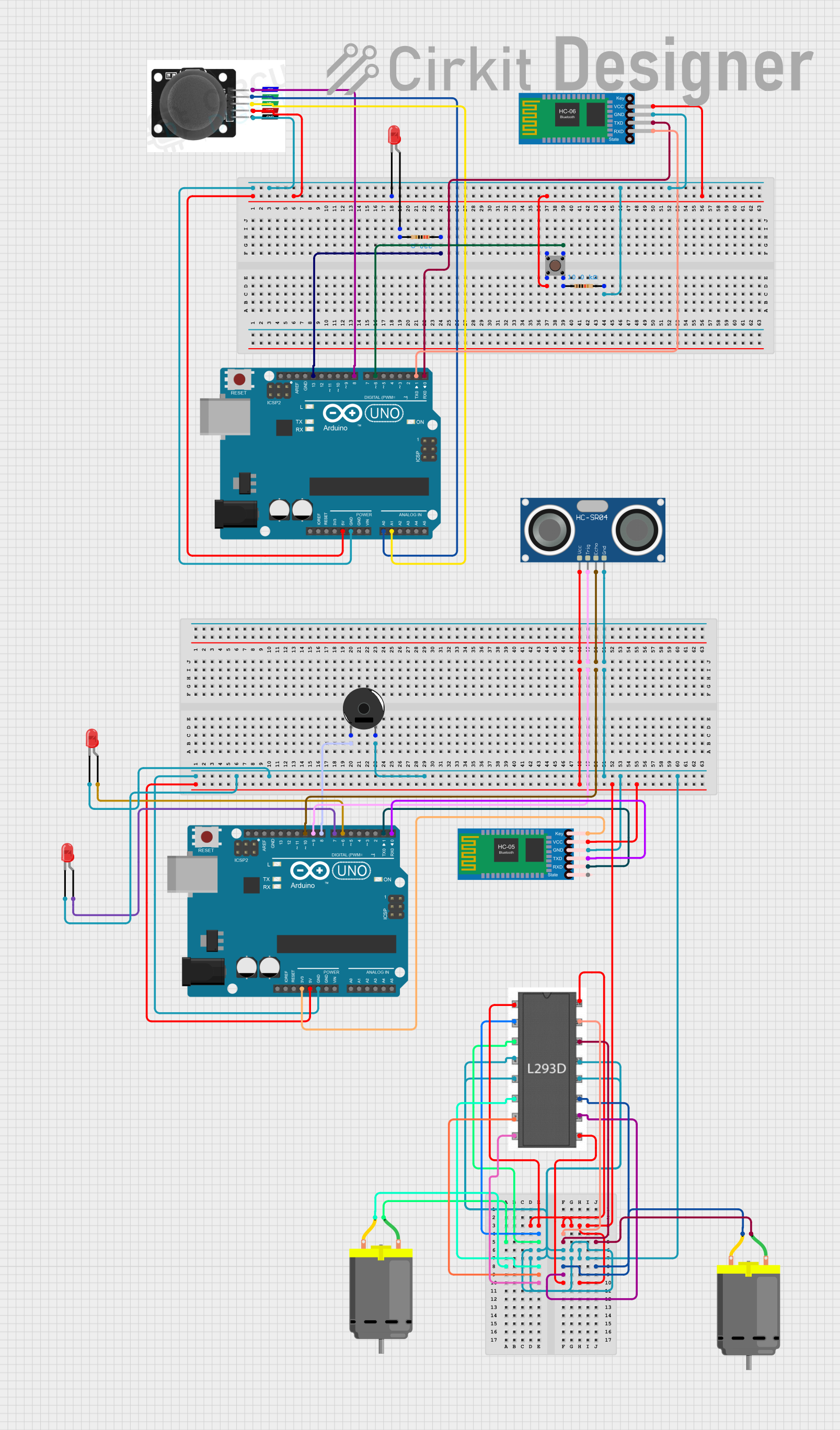
Circuit Documentation
Summary
This document provides a detailed overview of a circuit design that includes various components such as Arduino UNO boards, LEDs, resistors, a joystick module, a pushbutton, Bluetooth modules, a motor driver, a piezo buzzer, an ultrasonic sensor, and DC motors. The circuit is designed to interface these components with two Arduino UNO microcontrollers, which are programmed to control the circuit's operations.
Component List
Arduino UNO
- Description: A microcontroller board based on the ATmega328P.
- Pins: UNUSED, IOREF, Reset, 3.3V, 5V, GND, Vin, A0, A1, A2, A3, A4, A5, SCL, SDA, AREF, D13, D12, D11, D10, D9, D8, D7, D6, D5, D4, D3, D2, D1, D0
LED: Two Pin (red)
- Description: A red LED with two pins: cathode and anode.
- Pins: cathode, anode
Resistor (220 Ohms)
- Description: A resistor with a resistance of 220 Ohms.
- Pins: pin1, pin2
Resistor (10k Ohms)
- Description: A resistor with a resistance of 10k Ohms.
- Pins: pin1, pin2
Joystick Module
- Description: A joystick module with multiple pins for various controls.
- Pins: SW, VRY, VRX, VCC, GND
Pushbutton
- Description: A pushbutton with four pins.
- Pins: Pin 3 (out), Pin 4 (out), Pin 1 (in), Pin 2 (in)
Bluetooth HC-06
- Description: A Bluetooth module for wireless communication.
- Pins: VCC, GND, TXD, RXD
HC-05 Bluetooth Module
- Description: Another Bluetooth module for wireless communication.
- Pins: Key, VCC, TXD, RXD, State, GND
L293D Motor Driver
- Description: A motor driver IC for controlling DC motors.
- Pins: Enable 1,2, Input 1, Output 1, GND, Output 2, Input 2, Vcc2, Vcc1, Input 4, Output 4, Output 3, Input 3, Enable 3,4
Piezo Buzzer
- Description: A piezoelectric buzzer for sound output.
- Pins: pin 1, pin 2
HC-SR04 Ultrasonic Sensor
- Description: An ultrasonic sensor for distance measurement.
- Pins: VCC, TRIG, ECHO, GND
DC Motor
- Description: A DC motor with two pins.
- Pins: pin 1, pin 2
Wiring Details
Arduino UNO (1)
- D13: Connected to Resistor (220 Ohms) pin1
- 5V: Connected to Pushbutton Pin 2 (in), LED (red) cathode, Joystick Module VCC, Bluetooth HC-06 VCC
- D6: Connected to Pushbutton Pin 3 (out)
- GND: Connected to Resistor (10k Ohms) pin2, Joystick Module GND, Bluetooth HC-06 GND
- A0: Connected to Joystick Module VRY
- A1: Connected to Joystick Module VRX
- D8: Connected to Joystick Module SW
- D1: Connected to Bluetooth HC-06 RXD
- D0: Connected to Bluetooth HC-06 TXD
Arduino UNO (2)
- D8: Connected to Piezo Buzzer pin 1
- GND: Connected to Piezo Buzzer pin 2, HC-SR04 Ultrasonic Sensor GND, L293D GND, LED (red) cathode, HC-05 Bluetooth Module GND
- 5V: Connected to HC-SR04 Ultrasonic Sensor VCC, L293D Enable 1,2, L293D Enable 3,4, L293D Vcc1, HC-05 Bluetooth Module VCC
- D9: Connected to HC-SR04 Ultrasonic Sensor TRIG
- D10: Connected to HC-SR04 Ultrasonic Sensor ECHO
- D7: Connected to LED (red) anode
- D6: Connected to LED (red) anode
- D1: Connected to HC-05 Bluetooth Module RXD
- D0: Connected to HC-05 Bluetooth Module TXD
- 3.3V: Connected to HC-05 Bluetooth Module Key
Resistor (220 Ohms)
- pin1: Connected to Arduino UNO (1) D13
- pin2: Connected to LED (red) anode
Resistor (10k Ohms)
- pin1: Connected to Pushbutton Pin 4 (out)
- pin2: Connected to Arduino UNO (1) GND
Pushbutton
- Pin 2 (in): Connected to Arduino UNO (1) 5V
- Pin 3 (out): Connected to Arduino UNO (1) D6
- Pin 4 (out): Connected to Resistor (10k Ohms) pin1
Joystick Module
- VCC: Connected to Arduino UNO (1) 5V
- GND: Connected to Arduino UNO (1) GND
- VRY: Connected to Arduino UNO (1) A0
- VRX: Connected to Arduino UNO (1) A1
- SW: Connected to Arduino UNO (1) D8
Bluetooth HC-06
- VCC: Connected to Arduino UNO (1) 5V
- GND: Connected to Arduino UNO (1) GND
- RXD: Connected to Arduino UNO (1) D1
- TXD: Connected to Arduino UNO (1) D0
HC-05 Bluetooth Module
- Key: Connected to Arduino UNO (2) 3.3V
- VCC: Connected to Arduino UNO (2) 5V
- GND: Connected to Arduino UNO (2) GND
- RXD: Connected to Arduino UNO (2) D1
- TXD: Connected to Arduino UNO (2) D0
L293D Motor Driver
- GND: Connected to Arduino UNO (2) GND
- Enable 1,2: Connected to Arduino UNO (2) 5V
- Enable 3,4: Connected to Arduino UNO (2) 5V
- Vcc1: Connected to Arduino UNO (2) 5V
Piezo Buzzer
- pin 1: Connected to Arduino UNO (2) D8
- pin 2: Connected to Arduino UNO (2) GND
HC-SR04 Ultrasonic Sensor
- VCC: Connected to Arduino UNO (2) 5V
- TRIG: Connected to Arduino UNO (2) D9
- ECHO: Connected to Arduino UNO (2) D10
- GND: Connected to Arduino UNO (2) GND
DC Motor (1)
- pin 1: Connected to L293D Output 1
- pin 2: Connected to L293D Output 2
DC Motor (2)
- pin 1: Connected to L293D Output 4
- pin 2: Connected to L293D Output 3
Documented Code
Arduino UNO (1)
void setup() {
  // put your setup code here, to run once:

}

void loop() {
  // put your main code here, to run repeatedly:

}
Arduino UNO (2)
void setup() {
  // put your setup code here, to run once:

}

void loop() {
  // put your main code here, to run repeatedly:

}