
RFID-Enabled Access Control System with GSM Notification and Solenoid Lock
View and Edit Project In Cirkit Designer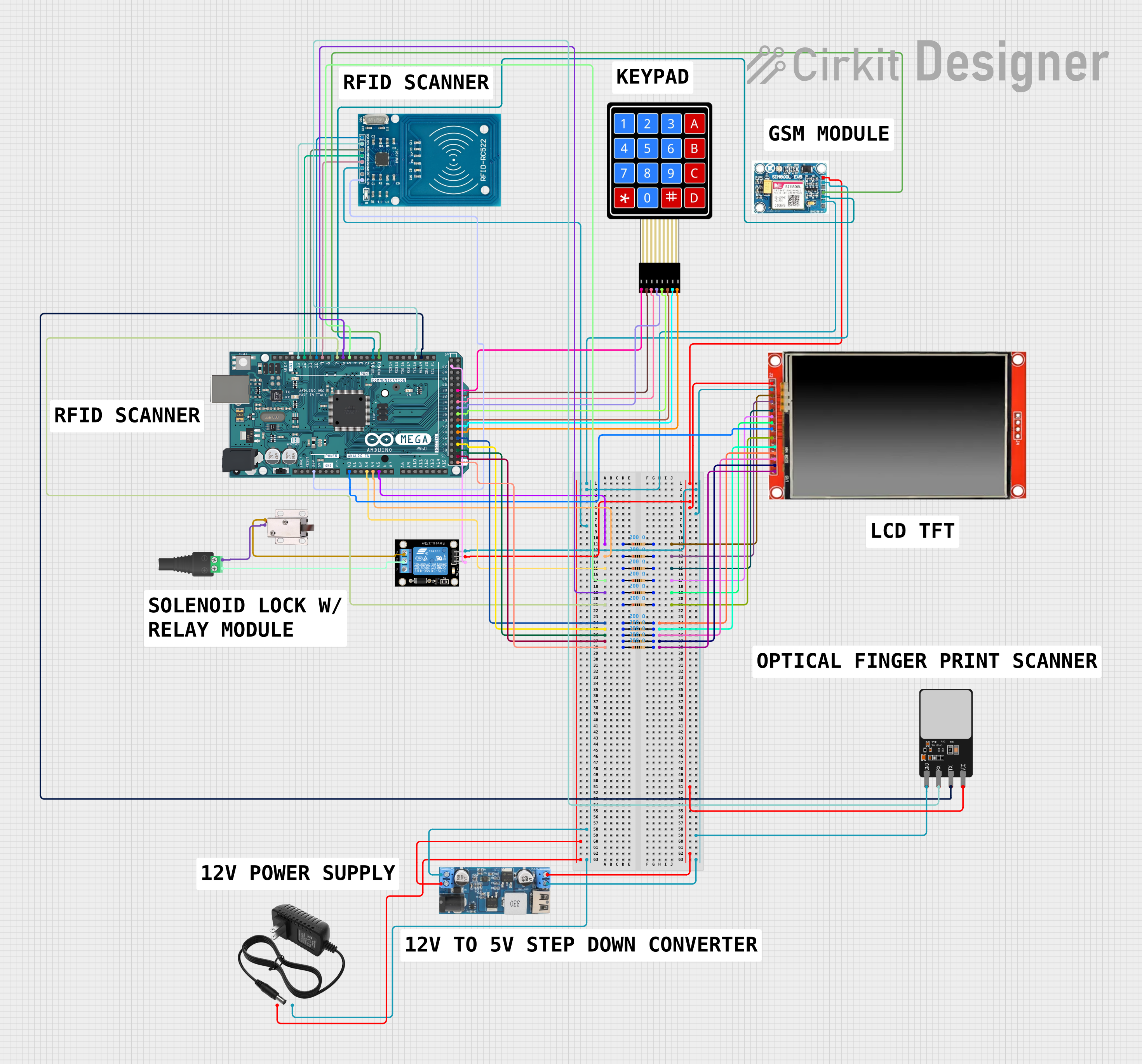
Circuit Documentation
Summary
This circuit is designed to control access using an RFID system. When a valid RFID card is presented to the RFID-RC522 reader, the Arduino Mega 2560 activates a relay that controls a 12V solenoid lock, granting access. The system also includes a SIM 800L GSM module for communication, a 4x4 keypad for input, and an LCD TFT screen for user interface. The circuit is powered by a 12V power supply, with a step-down converter providing 5V where needed. Multiple resistors are used for interfacing and pull-up/pull-down purposes.
Component List
RFID-RC522
- Description: An RFID reader/writer module for contactless communication using the 13.56MHz frequency.
- Pins: VCC (3.3V), RST, GND, IRQ, MISO, MOSI, SCK, SDA
12V Solenoid Lock
- Description: An electromagnetic lock that is actuated when 12V is applied.
- Pins: VCC, GND
12V Power Supply
- Description: Provides the 12V necessary to power the solenoid lock and other components through conversion.
- Pins: +, -
4X4 Membrane Matrix Keypad
- Description: A 16-button keypad for user input.
- Pins: R1, R2, R3, R4, C1, C2, C3, C4
SIM 800L V2.0 GSM
- Description: A GSM module for cellular communication.
- Pins: SIM_TXD, VDD, SIM.RXD, 5V/4V, GND, RST
Arduino Mega 2560
- Description: A microcontroller board based on the ATmega2560, with numerous digital and analog I/O pins.
- Pins: Multiple digital and analog pins, power, and ground.
Relay Module 1 Channel
- Description: An electrically operated switch that can be controlled by the Arduino.
- Pins: S, 5V, GND, NC, COM, NO
2.1mm Barrel Jack with Terminal Block
- Description: A connector for the power supply to interface with the circuit.
- Pins: POS, NEG
12V to 5V Step Down Power Converter
- Description: Converts the 12V input to a 5V output for components requiring 5V.
- Pins: VIN 9v-36v, VIN+, VIN-, USB OUTPUT 5V, 5v OUTPUT, GND
LCD TFT Screen ILI9488 HD
- Description: A color LCD screen for displaying information to the user.
- Pins: PEN, TDO, TDI, VCC (3.3~5V), GND, CS, RST, D/C, SDI(MOSI), SCK, BL, SDO(MISO), TCS, TCK
Resistor (200 Ohms)
- Description: A resistor with a resistance of 200 Ohms, used for various purposes in the circuit.
Fingerprint Scanner
- Description: A biometric sensor for fingerprint detection and verification.
- Pins: VCC, TX, RX, GND
Wiring Details
RFID-RC522
- VCC (3.3V) connected to Arduino Mega 2560 3V3
- RST connected to Arduino Mega 2560 D9 PWM
- GND connected to common ground
- IRQ not connected
- MISO connected to Arduino Mega 2560 D12 PWM
- MOSI connected to Arduino Mega 2560 D11 PWM
- SCK connected to Arduino Mega 2560 D13 PWM
- SDA connected to Arduino Mega 2560 D10 PWM
12V Solenoid Lock
- VCC connected to Relay Module 1 Channel NO
- GND connected to 2.1mm Barrel Jack with Terminal Block NEG
12V Power Supply
-
- connected to 12v to 5v Step Down Power Converter VIN+
-
- connected to common ground
4X4 Membrane Matrix Keypad
- R1 connected to Arduino Mega 2560 D31
- R2 connected to Arduino Mega 2560 D33
- R3 connected to Arduino Mega 2560 D35
- R4 connected to Arduino Mega 2560 D37
- C1 connected to Arduino Mega 2560 D39
- C2 connected to Arduino Mega 2560 D41
- C3 connected to Arduino Mega 2560 D43
- C4 connected to Arduino Mega 2560 D45
SIM 800L V2.0 GSM
- SIM_TXD connected to Arduino Mega 2560 D0 RX0
- VDD not connected
- SIM.RXD connected to Arduino Mega 2560 D1 TX0
- 5V/4V connected to 5V output from the step-down converter
- GND connected to common ground
- RST not connected
Relay Module 1 Channel
- S connected to Arduino Mega 2560 D22
- 5V connected to 5V output from the step-down converter
- GND connected to common ground
- NC not connected
- COM connected to 2.1mm Barrel Jack with Terminal Block POS
- NO connected to 12V Solenoid Lock VCC
LCD TFT Screen ILI9488 HD
- PEN connected to Resistor (200 Ohms) pin2
- TDO connected to Resistor (200 Ohms) pin2
- TDI connected to Resistor (200 Ohms) pin2
- VCC (3.3~5V) connected to 5V output from the step-down converter
- GND connected to common ground
- CS connected to Resistor (200 Ohms) pin2
- RST connected to Resistor (200 Ohms) pin2
- D/C connected to Resistor (200 Ohms) pin2
- SDI(MOSI) connected to Resistor (200 Ohms) pin2
- SCK connected to Resistor (200 Ohms) pin2
- BL connected to Arduino Mega 2560 A0
- SDO(MISO) connected to Resistor (200 Ohms) pin2
- TCS connected to Resistor (200 Ohms) pin2
- TCK connected to Resistor (200 Ohms) pin2
Fingerprint Scanner
- VCC connected to 5V output from the step-down converter
- TX connected to Arduino Mega 2560 D19/RX1
- RX connected to Arduino Mega 2560 D18/TX1
- GND connected to common ground
Documented Code
#include <SPI.h>
#include <MFRC522.h>

#define SS_PIN 10
#define RST_PIN 9
#define RELAY_PIN 22

MFRC522 mfrc522(SS_PIN, RST_PIN);  // Create MFRC522 instance

void setup() {
  Serial.begin(9600);  // Initialize serial communications
  SPI.begin();         // Init SPI bus
  mfrc522.PCD_Init();  // Init MFRC522
  pinMode(RELAY_PIN, OUTPUT);
  digitalWrite(RELAY_PIN, LOW);  // Ensure relay is off at start
  Serial.println("Place your card to the reader...");
  Serial.println();
}

void loop() {
  // Look for new cards
  if (!mfrc522.PICC_IsNewCardPresent()) {
    return;
  }

  // Select one of the cards
  if (!mfrc522.PICC_ReadCardSerial()) {
    return;
  }

  // Show UID on serial monitor
  Serial.print("UID tag :");
  String content = "";
  for (byte i = 0; i < mfrc522.uid.size; i++) {
    Serial.print(mfrc522.uid.uidByte[i] < 0x10 ? " 0" : " ");
    Serial.print(mfrc522.uid.uidByte[i], HEX);
    content.concat(String(mfrc522.uid.uidByte[i] < 0x10 ? " 0" : " "));
    content.concat(String(mfrc522.uid.uidByte[i], HEX));
  }
  Serial.println();
  content.toUpperCase();

  // Check if the UID matches a known card
  if (content.substring(1) == "YOUR_CARD_UID") {  // Replace YOUR_CARD_UID with the actual UID of your card
    Serial.println("Access Granted");
    digitalWrite(RELAY_PIN, HIGH);  // Activate relay
    delay(5000);                    // Keep relay on for 5 seconds
    digitalWrite(RELAY_PIN, LOW);   // Deactivate relay
  } else {
    Serial.println("Access Denied");
  }
}
This code is for the Arduino Mega 2560 and is responsible for reading RFID cards and controlling the relay based on the card's UID. The relay, in turn, controls the solenoid lock. The code includes setup and loop functions, SPI communication, and serial output for debugging.