
Wi-Fi Controlled RGB LED and Octocoupler with Light Sensor using Wemos D1 Mini
View and Edit Project In Cirkit Designer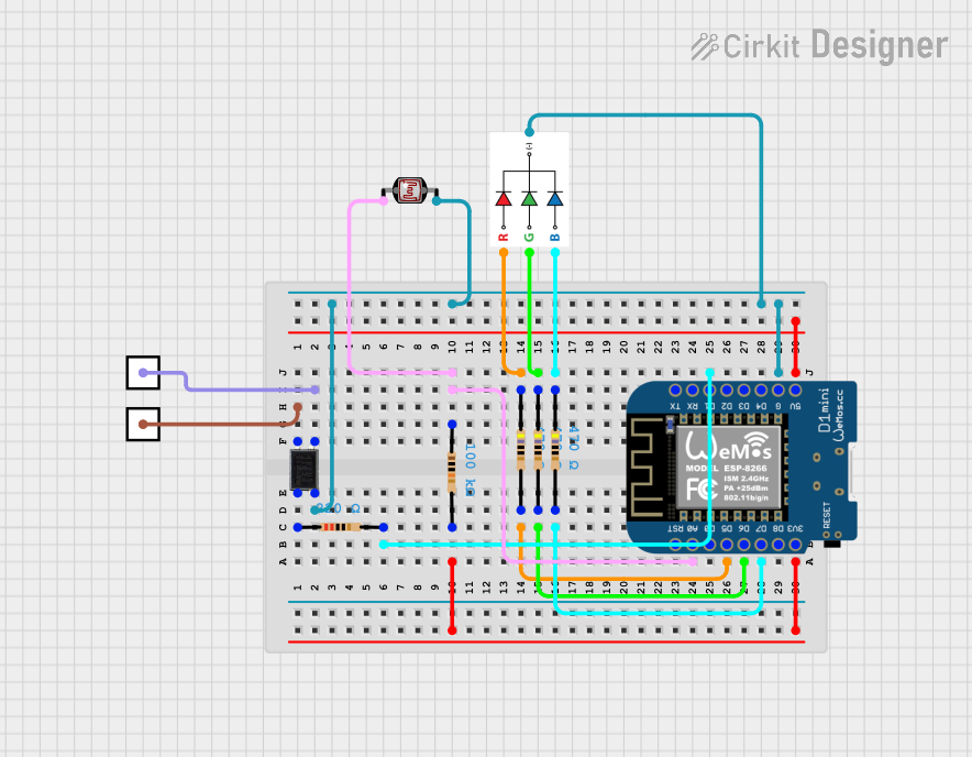
Circuit Documentation
Summary
This circuit is designed to control an RGB LED and an Octocoupler using a Wemos D1 Mini microcontroller. The RGB LED displays different colors based on the state of the pins, and the Octocoupler is controlled via a digital pin. Additionally, a Photocell (LDR) is used to adjust the brightness of the LED based on ambient light.
Component List
RGB LED
- Description: A light-emitting diode that can display red, green, and blue colors.
- Pins: B (Blue), G (Green), R (Red), GND (Ground)
Resistor (470 Ohms)
- Description: Limits the current to the RGB LED and Octocoupler.
- Pins: pin1, pin2
- Properties: Resistance: 470 Ohms
Resistor (220 Ohms)
- Description: Limits the current to the Octocoupler.
- Pins: pin1, pin2
- Properties: Resistance: 220 Ohms
Resistor (100k Ohms)
- Description: Forms a voltage divider with the Photocell.
- Pins: pin1, pin2
- Properties: Resistance: 100k Ohms
Wemos D1 Mini
- Description: A microcontroller based on the ESP8266, used to control the RGB LED and Octocoupler.
- Pins: RST, A0, D0, D5, D6, D7, D8, 3V3, 5V, G, D4, D3, D2, D1, RX, TX
Octocoupler
- Description: An optoelectronic device that isolates different sections of the circuit.
- Pins: Anode, Cathode, Collector, Emitter
Photocell (LDR)
- Description: A light-dependent resistor that changes resistance based on ambient light.
- Pins: pin 0, pin 1
External Connection
- Description: Represents external connections to the circuit.
- Pins: External
Wiring Details
RGB LED
- B (Blue): Connected to pin1 of a 470 Ohm resistor, which is connected to D7 of the Wemos D1 Mini.
- G (Green): Connected to pin1 of a 470 Ohm resistor, which is connected to D6 of the Wemos D1 Mini.
- R (Red): Connected to pin1 of a 470 Ohm resistor, which is connected to D5 of the Wemos D1 Mini.
- GND (Ground): Connected to the ground (G) of the Wemos D1 Mini.
Resistor (470 Ohms)
Instance 1:
- pin1: Connected to R pin of the RGB LED.
- pin2: Connected to D5 of the Wemos D1 Mini.
Instance 2:
- pin1: Connected to G pin of the RGB LED.
- pin2: Connected to D6 of the Wemos D1 Mini.
Instance 3:
- pin1: Connected to B pin of the RGB LED.
- pin2: Connected to D7 of the Wemos D1 Mini.
Resistor (220 Ohms)
- pin1: Connected to the Anode of the Octocoupler.
- pin2: Connected to D1 of the Wemos D1 Mini.
Resistor (100k Ohms)
- pin1: Connected to A0 of the Wemos D1 Mini.
- pin2: Connected to pin 0 of the Photocell (LDR).
Wemos D1 Mini
- D1: Connected to pin2 of a 220 Ohm resistor, which is connected to the Anode of the Octocoupler.
- D5: Connected to pin2 of a 470 Ohm resistor, which is connected to R pin of the RGB LED.
- D6: Connected to pin2 of a 470 Ohm resistor, which is connected to G pin of the RGB LED.
- D7: Connected to pin2 of a 470 Ohm resistor, which is connected to B pin of the RGB LED.
- A0: Connected to pin1 of a 100k Ohm resistor, which is connected to pin 0 of the Photocell (LDR).
- 3V3: Connected to pin2 of a 100k Ohm resistor.
- G (Ground): Connected to the Cathode of the Octocoupler, pin 1 of the Photocell (LDR), and GND of the RGB LED.
- 5V: Power supply for the Wemos D1 Mini.
Octocoupler
- Anode: Connected to pin1 of a 220 Ohm resistor, which is connected to D1 of the Wemos D1 Mini.
- Cathode: Connected to the ground (G) of the Wemos D1 Mini.
- Collector: Connected to an External Connection.
- Emitter: Connected to an External Connection.
Photocell (LDR)
- pin 0: Connected to pin1 of a 100k Ohm resistor, which is connected to A0 of the Wemos D1 Mini.
- pin 1: Connected to the ground (G) of the Wemos D1 Mini.
External Connection
- Instance 1: Connected to the Collector of the Octocoupler.
- Instance 2: Connected to the Emitter of the Octocoupler.
Code Documentation
/*
 * On Air Light Control
 * This code controls an RGB LED and an Octocoupler connected to a Wemos D1 Mini.
 * The RGB LED will display different colors based on the state of the pins.
 * - Blue: D7
 * - Green: D6
 * - Red: D5
 * The Octocoupler is controlled via pin D1.
 * The Photocell (LDR) is read via pin A0 to adjust the LED brightness.
 */

const int bluePin = D7;
const int greenPin = D6;
const int redPin = D5;
const int octoPin = D1;
const int ldrPin = A0;

void setup() {
  // Initialize the digital pins as outputs.
  pinMode(bluePin, OUTPUT);
  pinMode(greenPin, OUTPUT);
  pinMode(redPin, OUTPUT);
  pinMode(octoPin, OUTPUT);
  // Initialize the analog pin as input.
  pinMode(ldrPin, INPUT);
}

void loop() {
  // Read the value from the LDR
  int ldrValue = analogRead(ldrPin);
  // Map the LDR value to a brightness level (0-255)
  int brightness = map(ldrValue, 0, 1023, 0, 255);
  // Example sequence to light up the RGB LED with brightness control
  analogWrite(bluePin, brightness); // Turn on blue with brightness
  delay(1000); // Wait for a second
  analogWrite(bluePin, 0); // Turn off blue
  analogWrite(greenPin, brightness); // Turn on green with brightness
  delay(1000); // Wait for a second
  analogWrite(greenPin, 0); // Turn off green
  analogWrite(redPin, brightness); // Turn on red with brightness
  delay(1000); // Wait for a second
  analogWrite(redPin, 0); // Turn off red
  // Control the Octocoupler
  digitalWrite(octoPin, HIGH); // Turn on Octocoupler
  delay(1000); // Wait for a second
  digitalWrite(octoPin, LOW); // Turn off Octocoupler
}
This code initializes the pins connected to the RGB LED and the Octocoupler as outputs and the pin connected to the Photocell (LDR) as an input. In the loop, it reads the value from the LDR, maps it to a brightness level, and controls the RGB LED and Octocoupler accordingly.