Cirkit Designer
Your all-in-one circuit design IDE
Home /
Project Documentation
Wi-Fi Enabled Water Monitoring System with ESP8266
Circuit Documentation
Summary
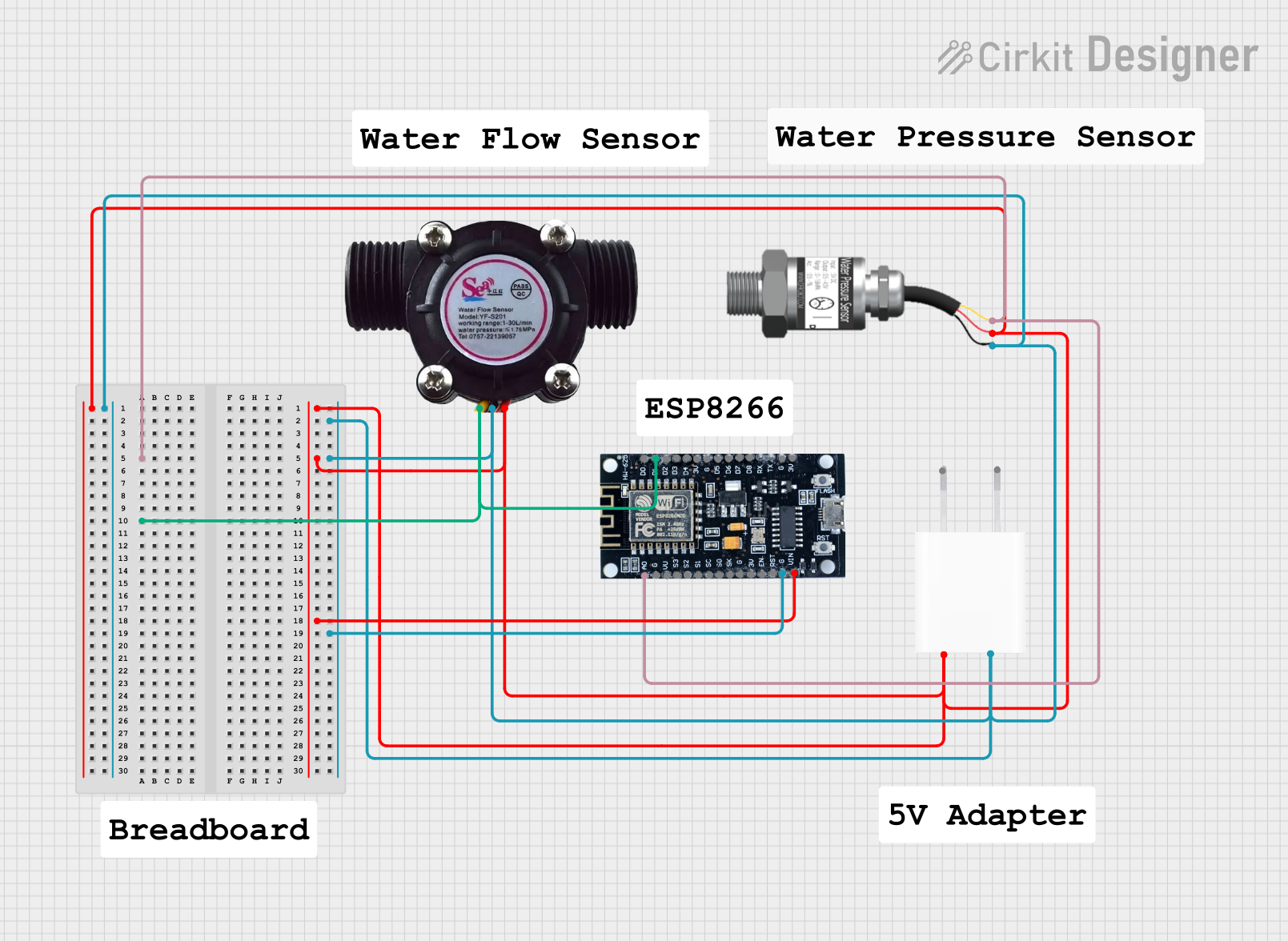
This document provides a detailed overview of a circuit designed to measure water pressure and flow using an ESP8266 microcontroller. The circuit includes a Gravity: Analog Water Pressure Sensor, a water flow sensor, and a 5V adapter to power the components. The sensors are connected to the ESP8266, which processes the data.
Component List
Gravity: Analog Water Pressure Sensor
- Description: Measures the water pressure in the system.
- Pins: Signal, VCC, GND
5V Adapter
- Description: Provides a 5V power supply to the circuit.
- Pins: AC In 1, AC In 2, 5V, GND
ESP8266
- Description: A microcontroller used to process sensor data and potentially communicate with other devices or networks.
- Pins: 3V, G, D8, D7, D6, D5, D4, D3, D2, D1, D0, A0, S3, S2, S1, SC, S0, SK, EN, VIN, RST, VU
Water Flow Sensor
- Description: Measures the flow rate of water in the system.
- Pins: Signal, Vcc, GND
Wiring Details
Gravity: Analog Water Pressure Sensor
- Signal pin is connected to the A0 pin of the ESP8266.
- VCC pin is connected to the 5V pin of the 5V Adapter and the VIN pin of the ESP8266.
- GND pin is connected to the GND pin of the 5V Adapter and the G pin of the ESP8266.
5V Adapter
- 5V pin is connected to the VCC pin of the Gravity: Analog Water Pressure Sensor, the Vcc pin of the Water Flow Sensor, and the VIN pin of the ESP8266.
- GND pin is connected to the GND pin of the Gravity: Analog Water Pressure Sensor, the GND pin of the Water Flow Sensor, and the G pin of the ESP8266.
ESP8266
- A0 pin is connected to the Signal pin of the Gravity: Analog Water Pressure Sensor.
- D1 pin is connected to the Signal pin of the Water Flow Sensor.
- VIN pin is connected to the 5V pin of the 5V Adapter.
- G pin is connected to the GND pin of the 5V Adapter.
Water Flow Sensor
- Signal pin is connected to the D1 pin of the ESP8266.
- Vcc pin is connected to the 5V pin of the 5V Adapter and the VIN pin of the ESP8266.
- GND pin is connected to the GND pin of the 5V Adapter and the G pin of the ESP8266.
Code
No code is provided for this circuit.
This document provides a comprehensive overview of the circuit, including a summary, detailed component list, wiring details, and code documentation. This should serve as a useful reference for understanding and replicating the circuit.