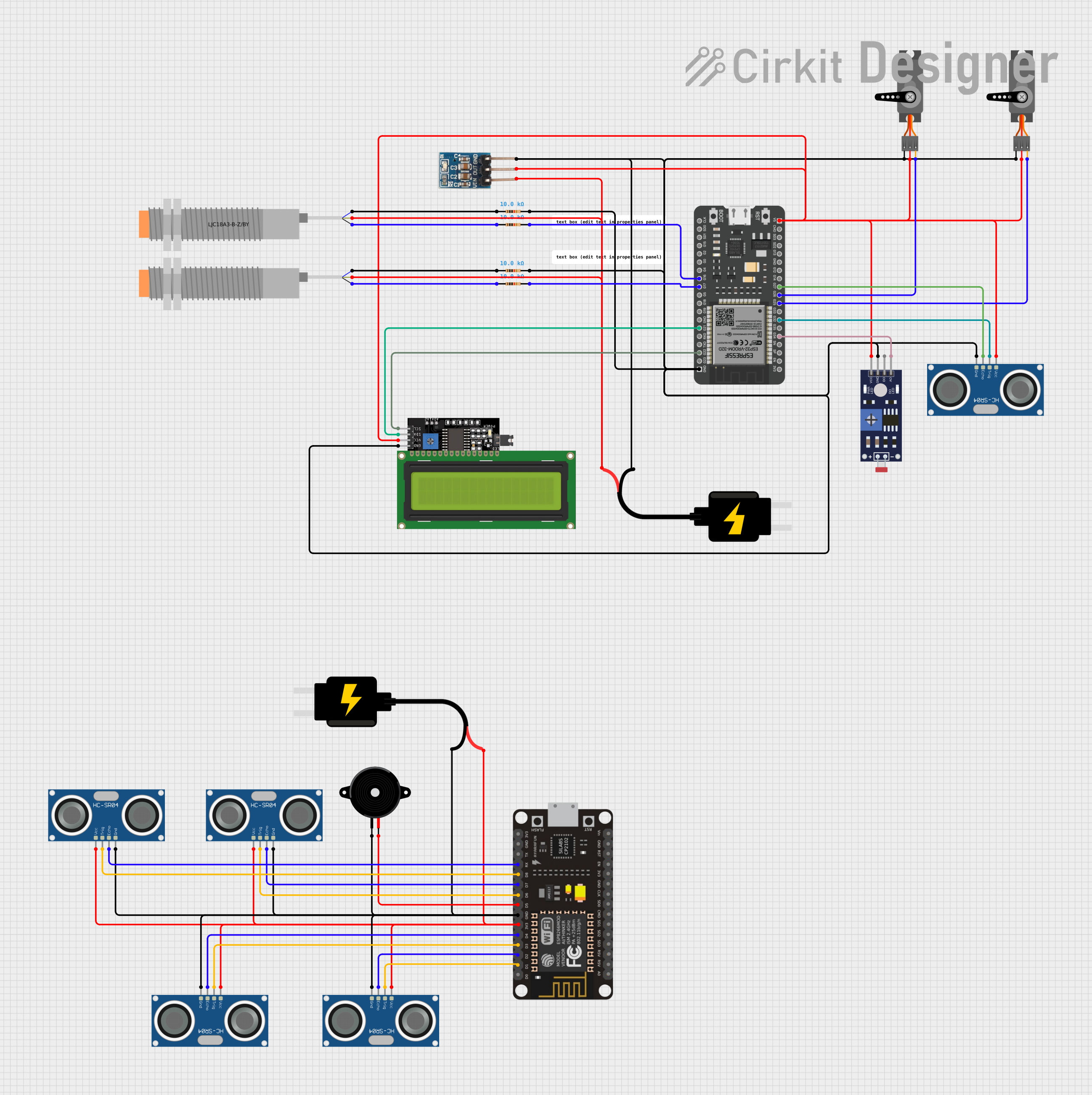
ESP32-Based Multi-Sensor Actuation System with LCD Feedback

Circuit Documentation
Summary
This circuit integrates various sensors, actuators, and microcontrollers to perform a range of functions. The core of the circuit is based on the ESP32 microcontroller, which is responsible for handling inputs from sensors like the photoresistor (LDR), HC-SR04 ultrasonic sensors, and capacitive and inductive proximity sensors. It also controls actuators such as servos and interfaces with an LCD display via I2C communication. An ESP-8266 controller is also included, which interacts with additional HC-SR04 ultrasonic sensors and a piezo speaker. Power regulation is managed by a 3.3V regulator and a 5V DC source. The circuit is designed to be versatile, catering to various sensing and control applications.
Component List
Microcontrollers
- ESP32 - 38 pins: A powerful microcontroller with Wi-Fi and Bluetooth capabilities, featuring a wide range of GPIO pins.
- ESP-8266 Controller: A Wi-Fi-enabled microcontroller used for IoT projects, with a set of digital and analog pins.
Sensors
- Photoresistor (LDR) Sensor (Wokwi Compatible): A light-sensitive sensor that changes resistance based on light intensity.
- HC-SR04 Ultrasonic Sensor: A sensor that measures distance by emitting ultrasonic waves and measuring the time taken for the echo to return.
- LJC18A3-B-Z/BY Capacitive Proximity Sensor: A sensor that detects the presence of objects based on changes in capacitance.
- LJ18A3-H-ZBX Inductive Proximity Sensor: A sensor that detects metallic objects based on electromagnetic induction.
Actuators
- Servo: An actuator capable of precise position control, commonly used for steering mechanisms in robotics and RC vehicles.
Power Supply
- DC Source 5V: Provides a stable 5V power supply to the circuit components.
- 3.3V regulator: Steps down voltage to 3.3V to power components that require a lower operating voltage.
Display
- LCD Display 16x4 I2C: A 16x4 character LCD display that communicates with the microcontroller via the I2C protocol.
Passive Components
- Resistor: A passive two-terminal electrical component that implements electrical resistance as a circuit element.
Output Devices
- Piezo Speaker: An electronic device that emits sound when an electric current is applied, used for generating tones and beeps.
Wiring Details
ESP32 - 38 pins
G34connected to Photoresistor Sensor AO pinG32connected to HC-SR04 Ultrasonic Sensor TRIG pinG25connected to Servo PWM pinG26connected to another Servo PWM pinG27connected to HC-SR04 Ultrasonic Sensor ECHO pin5Vconnected to various VCC pins of sensors and actuatorsGNDconnected to various GND pins of sensors and actuatorsG22connected to LCD Display SCL pinG21connected to LCD Display SDA pinG17connected to a Resistor pin2G16connected to another Resistor pin2
Photoresistor (LDR) Sensor (Wokwi Compatible)
VCCconnected to 5V power supplyGNDconnected to groundAOconnected to ESP32 G34 pin
HC-SR04 Ultrasonic Sensor
TRIGconnected to ESP32 G32 pinECHOconnected to ESP32 G27 pinVCCconnected to 5V power supplyGNDconnected to ground
Servo
PWMconnected to ESP32 G25 or G26 pinVCCconnected to 5V power supplyGNDconnected to ground
LCD Display 16x4 I2C
SCLconnected to ESP32 G22 pinSDAconnected to ESP32 G21 pinVCCconnected to 3.3V regulator outputGNDconnected to ground
Resistor
pin1connected to Capacitive or Inductive Proximity Sensor VO (BLU) pinpin2connected to ESP32 G17 or G16 pin
LJC18A3-B-Z/BY Capacitive Proximity Sensor
VO (BLU)connected to a Resistor pin1VI (BRN)connected to 5V power supplySIG (BLK)connected to a Resistor pin1
LJ18A3-H-ZBX Inductive Proximity Sensor
VO (BLU)connected to a Resistor pin1VI (BRN)connected to 5V power supplySIG (BLK)connected to a Resistor pin1
3.3V regulator
GNDconnected to groundOUTconnected to various VCC pins of sensors and actuatorsVinconnected to 5V power supply
ESP-8266 Controller
D1toD8connected to various TRIG and ECHO pins of HC-SR04 Ultrasonic SensorsRXconnected to HC-SR04 Ultrasonic Sensor ECHO pin3V3connected to HC-SR04 Ultrasonic Sensor VCC pinGNDconnected to ground
Piezo Speaker
pin1connected to groundpin2connected to ESP-8266 Controller D5 pin
Documented Code
No code was provided for the microcontrollers in the circuit. To fully document the circuit, the embedded code for the ESP32 and ESP-8266 controllers would be required. This code would typically initialize the hardware peripherals, manage sensor readings, control actuators, and handle communication protocols.