Cirkit Designer
Your all-in-one circuit design IDE
Home /
Project Documentation
Arduino UNO-Based Smart IR Sensor and RGB LED Control System with Servo Motors
Circuit Documentation
Summary
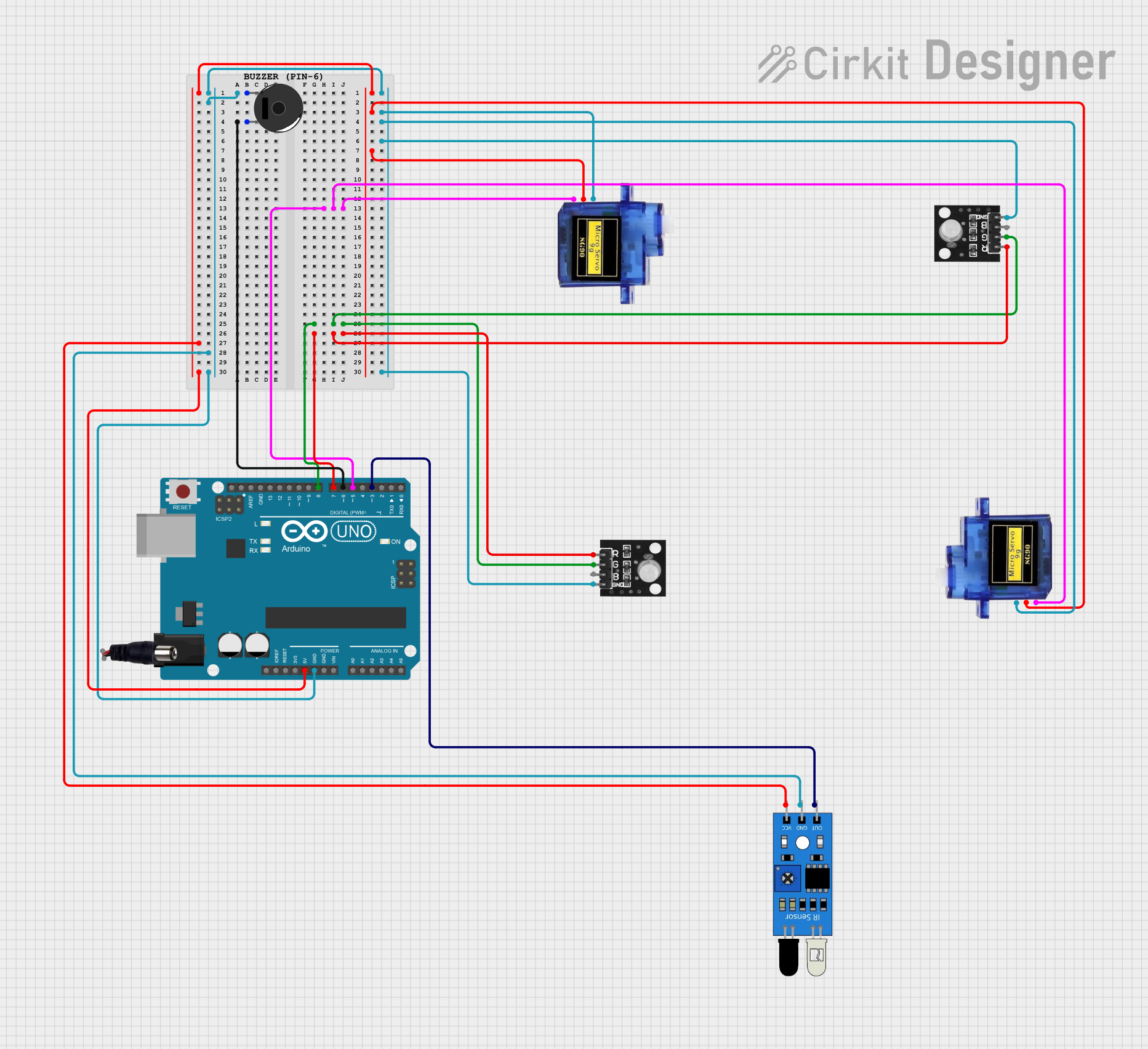
This document provides a detailed overview of a circuit that includes an Arduino UNO microcontroller, an IR sensor, RGB LED modules, Micro servo motors, a Piezo buzzer, and a power jack. The circuit is designed to interface these components with the Arduino UNO, allowing for various functionalities such as sensing, actuation, and visual/auditory feedback.
Component List
Arduino UNO
- Description: A microcontroller board based on the ATmega328P.
- Pins: UNUSED, IOREF, Reset, 3.3V, 5V, GND, Vin, A0, A1, A2, A3, A4, A5, SCL, SDA, AREF, D13, D12, D11, D10, D9, D8, D7, D6, D5, D4, D3, D2, D1, D0
IR Sensor
- Description: An infrared sensor used for detecting objects.
- Pins: out, gnd, vcc
RGB LED Module
- Description: A module containing Red, Green, and Blue LEDs.
- Pins: +VCC Red, +VCC Green, +VCC Blue, GND
Micro Servo 9G
- Description: A small servo motor used for precise control of angular position.
- Pins: GND, +5V, PWM
Piezo Buzzer
- Description: A buzzer that produces sound when a voltage is applied.
- Pins: pin 1, pin 2
Power Jack
- Description: A jack for connecting an external power supply.
- Pins: POSITIF, NEGATIF
Comment
- Description: A placeholder for comments in the circuit.
- Pins: None
Wiring Details
Arduino UNO
5V:
- Connected to vcc of IR Sensor
- Connected to +5V of Micro Servo 9G (two instances)
GND:
- Connected to pin 1 of Piezo Buzzer
- Connected to gnd of IR Sensor
- Connected to GND of Micro Servo 9G (two instances)
- Connected to GND of RGB LED Module (two instances)
D8:
- Connected to +VCC Green of RGB LED Module (two instances)
D7:
- Connected to +VCC Red of RGB LED Module (two instances)
D6:
- Connected to pin 2 of Piezo Buzzer
D5:
- Connected to PWM of Micro Servo 9G (two instances)
D3:
- Connected to out of IR Sensor
IR Sensor
vcc:
- Connected to 5V of Arduino UNO
gnd:
- Connected to GND of Arduino UNO
out:
- Connected to D3 of Arduino UNO
RGB LED Module
+VCC Green:
- Connected to D8 of Arduino UNO
+VCC Red:
- Connected to D7 of Arduino UNO
GND:
- Connected to GND of Arduino UNO
Micro Servo 9G
+5V:
- Connected to 5V of Arduino UNO
GND:
- Connected to GND of Arduino UNO
PWM:
- Connected to D5 of Arduino UNO
Piezo Buzzer
pin 1:
- Connected to GND of Arduino UNO
pin 2:
- Connected to D6 of Arduino UNO
Power Jack
POSITIF:
- Not connected in the provided net list
NEGATIF:
- Not connected in the provided net list
Documented Code
Arduino UNO Code (sketch.ino)
void setup() {
  // put your setup code here, to run once:

}

void loop() {
  // put your main code here, to run repeatedly:

}
Documentation (documentation.txt)
This document provides a comprehensive overview of the circuit, including the components used, their connections, and the code running on the Arduino UNO.