
Circuit Documentation
Summary
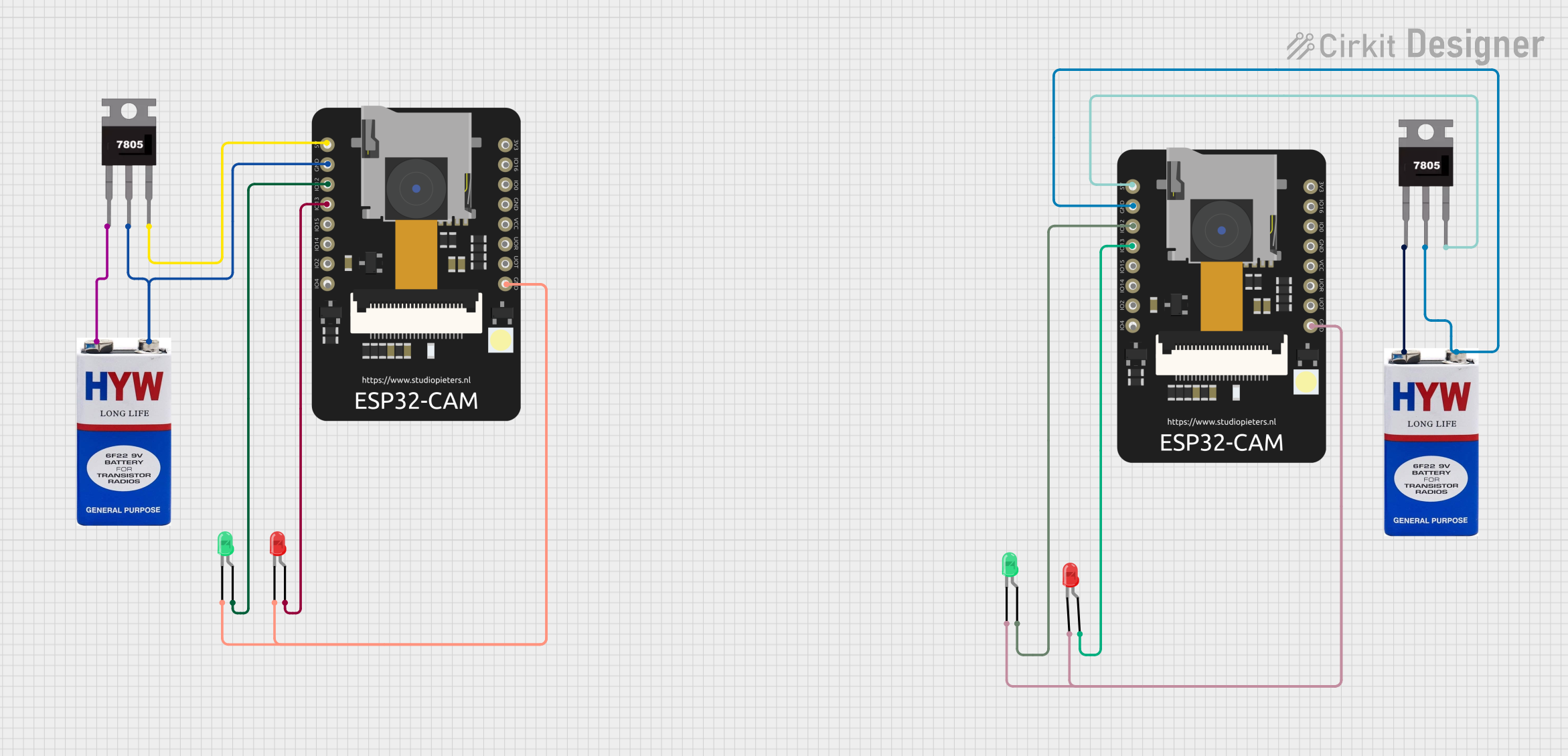
This circuit involves two ESP32 CAM modules, each powered by a 9V battery through a 7805 voltage regulator. Each ESP32 CAM controls two LEDs (one red and one green). The LEDs are connected to the GPIO pins of the ESP32 CAM modules.
Component List
ESP32 CAM
- Description: A microcontroller with integrated Wi-Fi and Bluetooth, suitable for camera applications.
- Pins: 5V, GND, GPIO12, GPIO13, GPIO15, GPIO14, GPIO2, GPIO4, 3.3V, GPIO16, GPIO0, 3.3V / 5V / P_OUT, GPIO3 / RX, GPIO1 / TX
9V Battery
- Description: A standard 9V battery used to power the circuit.
- Pins: +, -
LED: Two Pin (red)
- Description: A red LED with two pins (anode and cathode).
- Pins: cathode, anode
LED: Two Pin (green)
- Description: A green LED with two pins (anode and cathode).
- Pins: cathode, anode
7805 Voltage Regulator
- Description: A voltage regulator that converts 9V to 5V.
- Pins: Vin, Gnd, Vout
Wiring Details
ESP32 CAM (1)
- 5V: Connected to Vout of 7805 Voltage Regulator (1)
- GND: Connected to Gnd of 7805 Voltage Regulator (1) and - of 9V Battery (1)
- GPIO12: Connected to anode of Green LED (1)
- GPIO13: Connected to anode of Red LED (1)
- GND: Connected to cathode of Red LED (1) and cathode of Green LED (1)
ESP32 CAM (2)
- 5V: Connected to Vout of 7805 Voltage Regulator (2)
- GND: Connected to Gnd of 7805 Voltage Regulator (2) and - of 9V Battery (2)
- GPIO12: Connected to anode of Green LED (2)
- GPIO13: Connected to anode of Red LED (2)
- GND: Connected to cathode of Red LED (2) and cathode of Green LED (2)
9V Battery (1)
- +: Connected to Vin of 7805 Voltage Regulator (1)
- -: Connected to Gnd of 7805 Voltage Regulator (1) and GND of ESP32 CAM (1)
9V Battery (2)
- +: Connected to Vin of 7805 Voltage Regulator (2)
- -: Connected to Gnd of 7805 Voltage Regulator (2) and GND of ESP32 CAM (2)
7805 Voltage Regulator (1)
- Vin: Connected to + of 9V Battery (1)
- Gnd: Connected to - of 9V Battery (1) and GND of ESP32 CAM (1)
- Vout: Connected to 5V of ESP32 CAM (1)
7805 Voltage Regulator (2)
- Vin: Connected to + of 9V Battery (2)
- Gnd: Connected to - of 9V Battery (2) and GND of ESP32 CAM (2)
- Vout: Connected to 5V of ESP32 CAM (2)
LED: Two Pin (red) (1)
- anode: Connected to GPIO13 of ESP32 CAM (1)
- cathode: Connected to GND of ESP32 CAM (1)
LED: Two Pin (red) (2)
- anode: Connected to GPIO13 of ESP32 CAM (2)
- cathode: Connected to GND of ESP32 CAM (2)
LED: Two Pin (green) (1)
- anode: Connected to GPIO12 of ESP32 CAM (1)
- cathode: Connected to GND of ESP32 CAM (1)
LED: Two Pin (green) (2)
- anode: Connected to GPIO12 of ESP32 CAM (2)
- cathode: Connected to GND of ESP32 CAM (2)
Code
No code is provided for this circuit.