Cirkit Designer
Your all-in-one circuit design IDE
Home /
Project Documentation
Battery-Powered Light-Dependent LED Circuit
Circuit Documentation
Summary
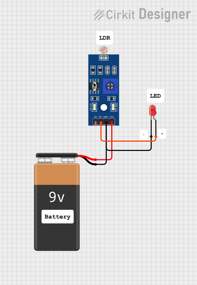
This document provides a detailed description of a simple circuit that includes a Light Dependent Resistor (LDR), a red LED, and a 9V battery. The circuit is designed to control the LED based on the light intensity detected by the LDR.
Component List
LDR (Light Dependent Resistor)
- Pins: A0, D0, GND, VCC
- Description: A sensor that changes its resistance based on the light intensity.
- Purpose in Circuit: To detect light intensity and control the LED accordingly.
LED: Two Pin (red)
- Pins: Cathode, Anode
- Description: A red light-emitting diode.
- Purpose in Circuit: To emit light when powered.
9V Battery
- Pins: -, +
- Description: A 9V power source.
- Purpose in Circuit: To provide power to the circuit.
Comment
- Description: Placeholder for comments in the circuit design.
- Purpose in Circuit: Not applicable.
Wiring Details
LDR (Light Dependent Resistor)
- Pin A0: Not connected.
- Pin D0: Connected to the anode of the LED.
- Pin GND: Connected to the cathode of the LED and the negative terminal of the 9V battery.
- Pin VCC: Connected to the positive terminal of the 9V battery.
LED: Two Pin (red)
- Pin Anode: Connected to pin D0 of the LDR.
- Pin Cathode: Connected to pin GND of the LDR and the negative terminal of the 9V battery.
9V Battery
- Pin -: Connected to pin GND of the LDR and the cathode of the LED.
- Pin +: Connected to pin VCC of the LDR.
Code
There is no embedded code associated with this circuit.
This document provides a comprehensive overview of the circuit, including the components used, their connections, and their roles within the circuit.