ESP32-Based Pulse Oximeter with USB-C Charging

Circuit Documentation
Summary
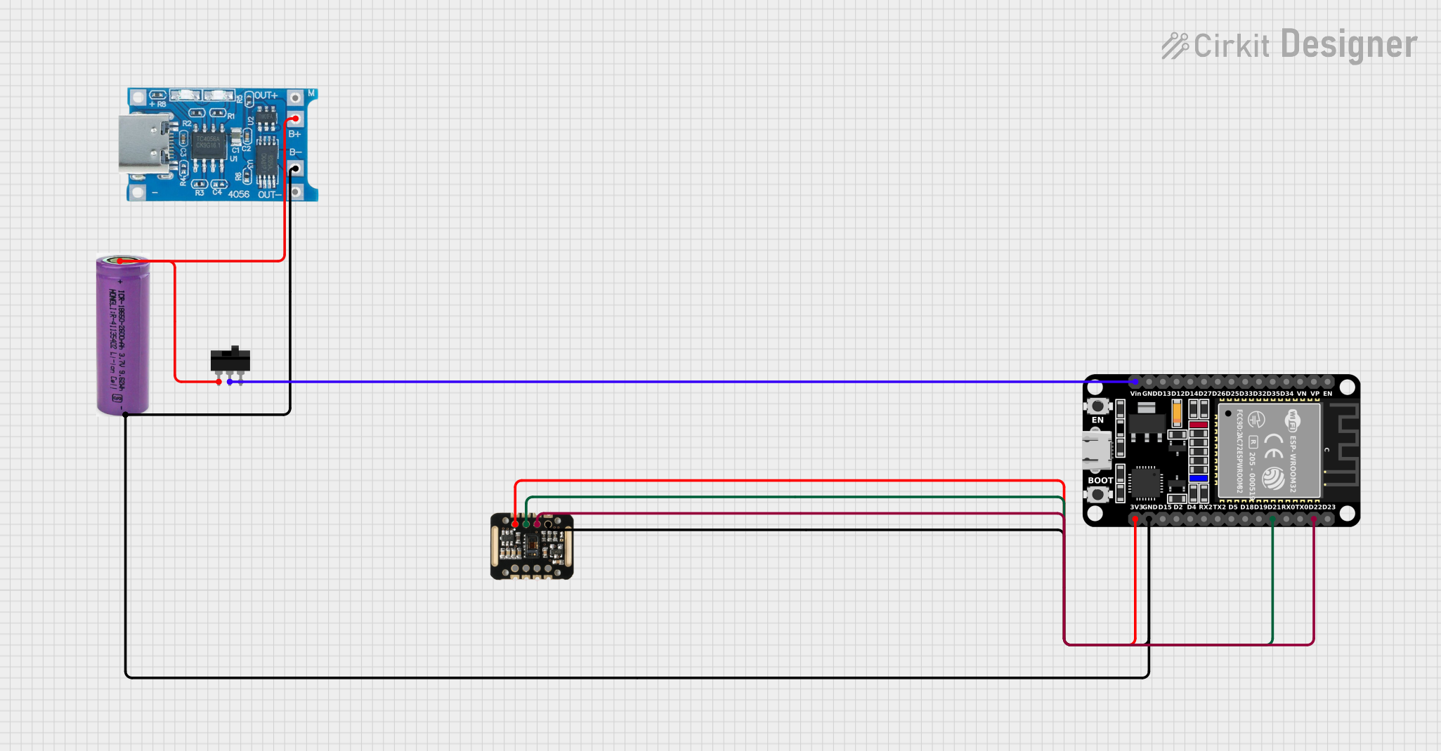
The circuit in question appears to be designed for a wearable or portable device, given the presence of a battery, a charging module, and a MAX30100 sensor, which is commonly used for measuring heart rate and blood oxygen levels. The ESP32 microcontroller serves as the central processing unit, interfacing with the MAX30100 sensor and managing power from the battery through a toggle switch. The TP4056 charging module is included to manage battery charging via a USB Type-C connection.
Component List
ESP32 (30 pin)
- Description: A microcontroller with Wi-Fi and Bluetooth capabilities, featuring a wide range of GPIO pins for interfacing with various peripherals.
- Purpose: Acts as the main controller for the circuit, processing sensor data and managing communication.
3.3v Battery
- Description: A power source for the circuit, likely a lithium-ion or lithium-polymer battery.
- Purpose: Provides power to the ESP32 and other components in the circuit.
TP4056 Type-C Charging Module
- Description: A charging module with a USB Type-C port for charging the battery.
- Purpose: Manages the charging of the 3.3v battery and provides power regulation.
MAX30100
- Description: An integrated pulse oximetry and heart-rate sensor.
- Purpose: Measures heart rate and blood oxygen levels, interfacing with the ESP32 for data processing.
Toggle Switch
- Description: A simple switch with a single pole double throw (SPDT) configuration.
- Purpose: Allows the user to manually turn the power supply to the ESP32 on or off.
Wiring Details
ESP32 (30 pin)
- Vin: Connected to the common terminal (COM) of the Toggle Switch.
- GND: Common ground with MAX30100, 3.3v battery, and TP4056 Charging Module.
- 3V3: Powers the MAX30100 sensor.
- D21 (SDA): I2C data line connected to the SDA pin of the MAX30100.
- D22 (SCL): I2C clock line connected to the SCL pin of the MAX30100.
3.3v Battery
- + (Positive): Connected to the B+ pin of the TP4056 Charging Module and L1 of the Toggle Switch.
- - (Negative): Common ground with other components.
TP4056 Type-C Charging Module
- B+: Connected to the positive terminal of the 3.3v battery.
- B-: Common ground with other components.
- OUT+: Not connected in the provided net list.
- OUT-: Not connected in the provided net list.
MAX30100
- VIN: Powered by the 3V3 output from the ESP32.
- GND: Common ground with other components.
- SDA: Connected to the D21 pin of the ESP32 for I2C data.
- SCL: Connected to the D22 pin of the ESP32 for I2C clock.
- RD, IRD, INT: Not connected in the provided net list.
Toggle Switch
- COM: Connected to the Vin pin of the ESP32.
- L1: Connected to the positive terminal of the 3.3v battery.
- L2: Not connected in the provided net list.
Documented Code
No code was provided for the microcontroller(s) in the circuit. For a functional circuit, embedded code would be required to initialize and manage the I2C communication with the MAX30100 sensor, handle sensor data processing, and manage power states. The code would typically be written in C or C++ and uploaded to the ESP32 using an IDE such as the Arduino IDE or ESP-IDF.