
Arduino Nano Controlled Joystick with NRF24L01 Wireless Communication
View and Edit Project In Cirkit Designer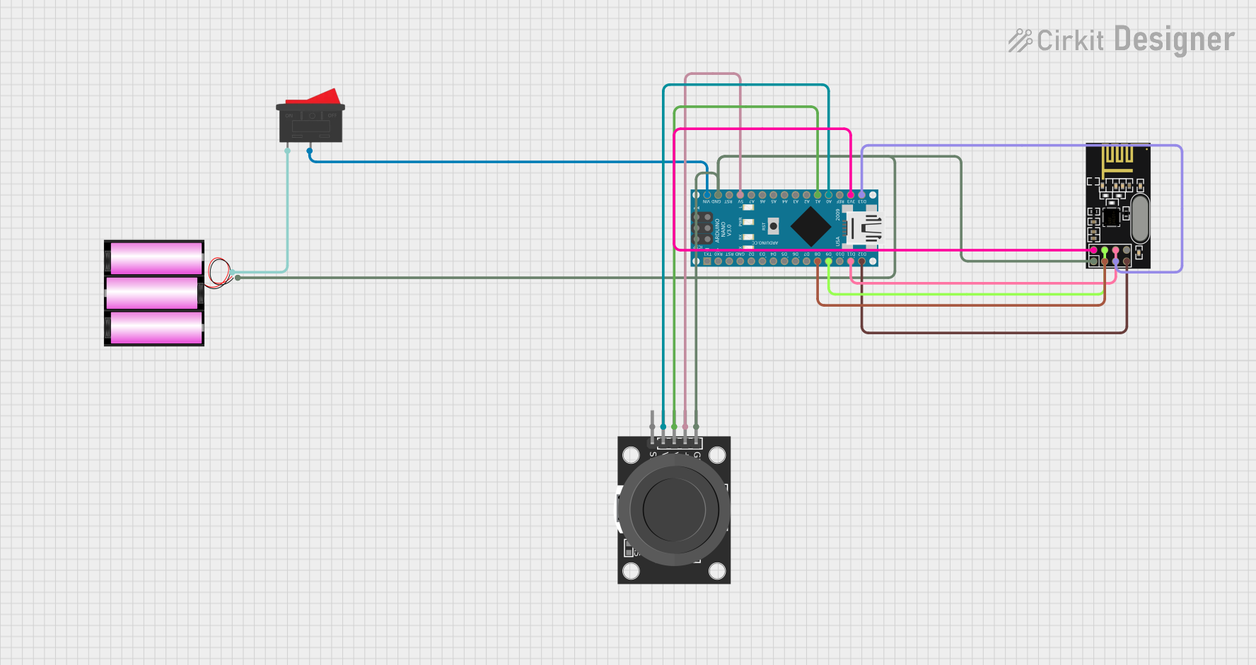
Circuit Documentation
Summary of the Circuit
This circuit is designed to interface an Arduino Nano with an NRF24L01 wireless transceiver module and a KY-023 Dual Axis Joystick Module. The Arduino Nano serves as the central processing unit, controlling the NRF24L01 for wireless communication and reading inputs from the joystick. A 12V battery provides power to the system, with a rocker switch included to control power delivery to the Arduino Nano. The NRF24L01 is powered by the 3.3V output from the Arduino Nano to match its operating voltage.
Component List
Rocker Switch
- Description: A simple on-off switch used to control the power supply to the circuit.
- Pins: 2 (1, 2)
Battery 12V
- Description: A 12-volt battery that serves as the power source for the circuit.
- Pins: 2 (+, -)
NRF24L01
- Description: A wireless transceiver module for enabling wireless communication.
- Pins: 8 (IRQ (not used), MOSI, CSN, VCC (3V), GND, CE, SCK, MISO)
Arduino Nano
- Description: A compact microcontroller board based on the ATmega328P, which is the brain of the circuit.
- Pins: 28 (D1/TX, D0/RX, RESET, GND, D2, D3, D4, D5, D6, D7, D8, D9, D10, D11/MOSI, D12/MISO, VIN, 5V, A7, A6, A5, A4, A3, A2, A1, A0, AREF, 3V3, D13/SCK)
KY-023 Dual Axis Joystick Module
- Description: A joystick module that provides two analog axis inputs and one digital input.
- Pins: 5 (GND, +5V, VRx, VRy, SW)
Wiring Details
Rocker Switch
- Pin 1: Connected to the positive terminal of the 12V battery.
- Pin 2: Connected to the VIN pin of the Arduino Nano.
Battery 12V
- Positive (+): Connected to pin 1 of the Rocker Switch.
- Negative (-): Connected to the GND pins of the KY-023 Joystick Module, NRF24L01, and Arduino Nano.
NRF24L01
- IRQ (not used): Not connected.
- MOSI: Connected to D11/MOSI of the Arduino Nano.
- CSN: Connected to D9 of the Arduino Nano.
- VCC (3V): Connected to 3V3 of the Arduino Nano.
- GND: Connected to the negative terminal of the 12V battery.
- CE: Connected to D8 of the Arduino Nano.
- SCK: Connected to D13/SCK of the Arduino Nano.
- MISO: Connected to D12/MISO of the Arduino Nano.
Arduino Nano
- VIN: Connected to pin 2 of the Rocker Switch.
- GND: Connected to the negative terminal of the 12V battery.
- 5V: Connected to the +5V pin of the KY-023 Joystick Module.
- A0: Connected to VRy of the KY-023 Joystick Module.
- A1: Connected to VRx of the KY-023 Joystick Module.
- D8, D9, D11/MOSI, D12/MISO, D13/SCK, 3V3: Connected to corresponding pins on the NRF24L01.
KY-023 Dual Axis Joystick Module
- GND: Connected to the negative terminal of the 12V battery.
- +5V: Connected to the 5V pin of the Arduino Nano.
- VRx: Connected to A1 of the Arduino Nano.
- VRy: Connected to A0 of the Arduino Nano.
- SW: Not connected in the provided net list.
Documented Code
Arduino Nano Code (sketch.ino)
void setup() {
  // put your setup code here, to run once:

}

void loop() {
  // put your main code here, to run repeatedly:

}
Additional Documentation (documentation.txt)
No additional documentation code was provided.