
Arduino Mega 2560 Flex Sensor Controlled LED Brightness System with MPU6050
View and Edit Project In Cirkit Designer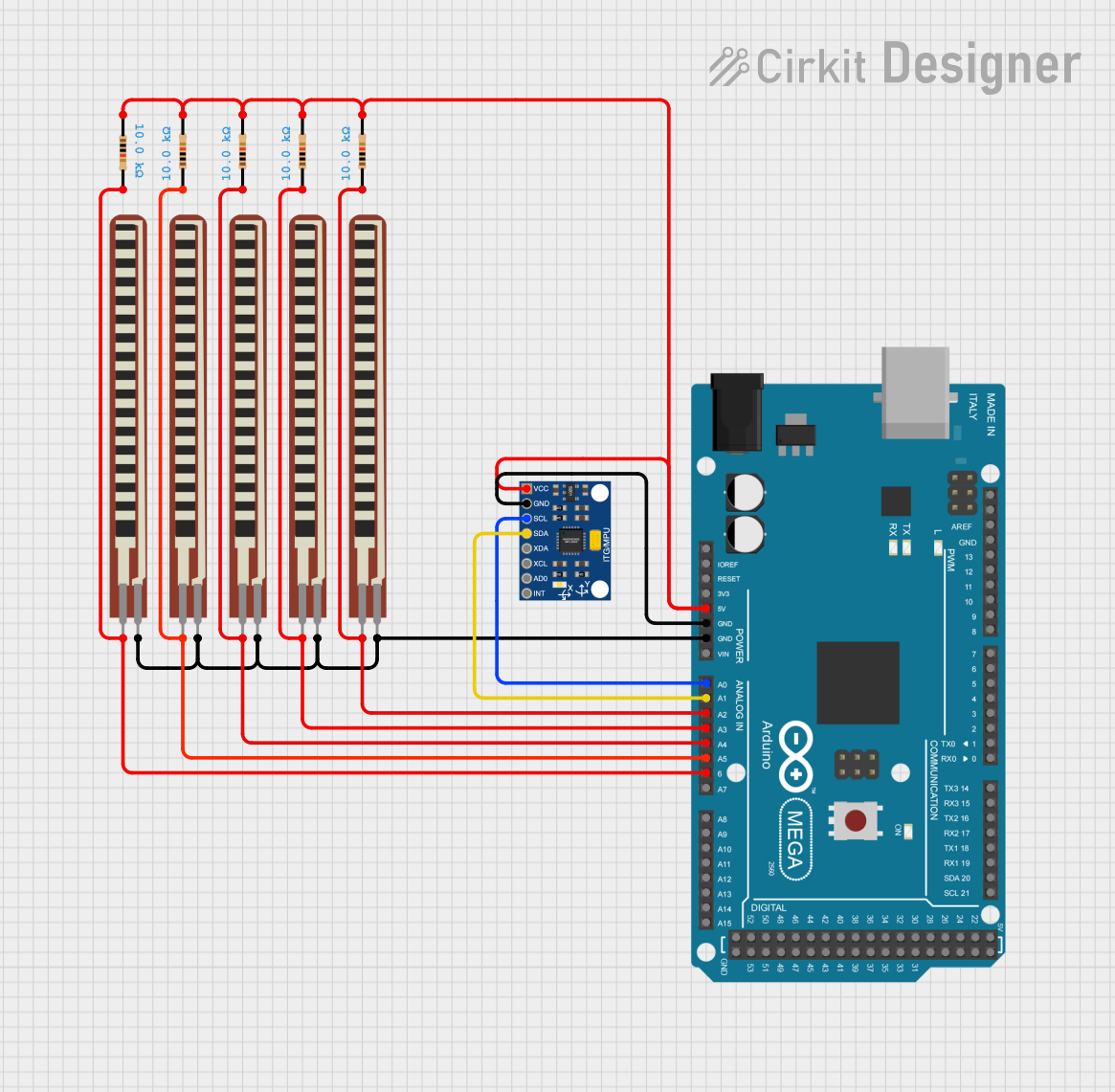
Circuit Documentation
Summary
This circuit involves an Arduino Mega 2560 microcontroller interfaced with an InvenSense MPU6050 sensor and multiple flex resistors. The circuit reads values from the flex sensors and controls the brightness of LEDs based on these readings. The MPU6050 sensor provides additional data, and the Arduino handles the processing and control logic.
Component List
InvenSense MPU6050
- Description: 6-axis motion tracking device.
- Pins: VCC, GND, SCL, SDA, XDA, XCL, AD0, INT
2.2 inch Basic Flex Resistor
- Description: Flex sensor used to measure bending.
- Pins: Pin 2, Pin 1
Arduino Mega 2560
- Description: Microcontroller board based on the ATmega2560.
- Pins: IOREF, RESET, 3V3, 5V, GND, VIN, A0-A15, D0-D53, SDA, SCL, AREF
Resistor (10k Ohms)
- Description: Resistor with a resistance of 10k Ohms.
- Pins: pin1, pin2
Wiring Details
InvenSense MPU6050
VCC connected to:
- Resistor pin2
- Arduino Mega 2560 5V
- Resistor pin1
- Resistor pin2
- Resistor pin2
- Resistor pin2
GND connected to:
- Arduino Mega 2560 GND
SCL connected to:
- Arduino Mega 2560 A0
SDA connected to:
- Arduino Mega 2560 A1
2.2 inch Basic Flex Resistor
Pin 2 connected to:
- Arduino Mega 2560 A4
- Resistor pin1
Pin 1 connected to:
- Arduino Mega 2560 GND
- Other flex resistors' Pin 1
Pin 2 connected to:
- Arduino Mega 2560 A5
- Resistor pin1
Pin 2 connected to:
- Arduino Mega 2560 A2
- Resistor pin1
Pin 2 connected to:
- Arduino Mega 2560 A3
- Resistor pin1
Pin 2 connected to:
- Arduino Mega 2560 A6
- Resistor pin2
Arduino Mega 2560
5V connected to:
- InvenSense MPU6050 VCC
- Resistor pin2
- Resistor pin1
- Resistor pin2
- Resistor pin2
- Resistor pin2
GND connected to:
- InvenSense MPU6050 GND
- Flex Resistor Pin 1
A0 connected to:
- InvenSense MPU6050 SCL
A1 connected to:
- InvenSense MPU6050 SDA
A2 connected to:
- Flex Resistor Pin 2
- Resistor pin1
A3 connected to:
- Flex Resistor Pin 2
- Resistor pin1
A4 connected to:
- Flex Resistor Pin 2
- Resistor pin1
A5 connected to:
- Flex Resistor Pin 2
- Resistor pin1
A6 connected to:
- Flex Resistor Pin 2
- Resistor pin2
Resistor (10k Ohms)
pin2 connected to:
- InvenSense MPU6050 VCC
- Arduino Mega 2560 5V
- Resistor pin1
- Resistor pin2
- Resistor pin2
- Resistor pin2
pin1 connected to:
- Arduino Mega 2560 A4
- Flex Resistor Pin 2
pin1 connected to:
- Arduino Mega 2560 A5
- Flex Resistor Pin 2
pin1 connected to:
- Arduino Mega 2560 A2
- Flex Resistor Pin 2
pin1 connected to:
- Arduino Mega 2560 A3
- Flex Resistor Pin 2
pin2 connected to:
- Arduino Mega 2560 A6
- Flex Resistor Pin 2
Code Documentation
/*
 * Arduino Mega 2560 Sketch
 * This sketch reads values from 5 flex sensors connected to analog pins A2, A3,
 * A4, A5, and A6. Based on the sensor readings, it controls 5 LEDs connected to
 * digital PWM pins D2, D3, D4, D5, and D6. The LEDs will change their brightness
 * according to the flex sensor readings.
 */

const int flexPins[5] = {A2, A3, A4, A5, A6};
const int ledPins[5] = {2, 3, 4, 5, 6};

void setup() {
  // Initialize serial communication
  Serial.begin(9600);
  // Set LED pins as output
  for (int i = 0; i < 5; i++) {
    pinMode(ledPins[i], OUTPUT);
  }
}

void loop() {
  for (int i = 0; i < 5; i++) {
    int sensorValue = analogRead(flexPins[i]);
    Serial.print("Flex sensor ");
    Serial.print(i);
    Serial.print(": ");
    Serial.println(sensorValue);
    int ledBrightness = map(sensorValue, 0, 1023, 0, 255);
    analogWrite(ledPins[i], ledBrightness); // Adjust LED brightness
  }
  delay(500); // Delay for half a second
}
This code initializes the Arduino Mega 2560 to read values from the flex sensors and adjust the brightness of LEDs accordingly. The sensor values are also printed to the serial monitor for debugging and monitoring purposes.