
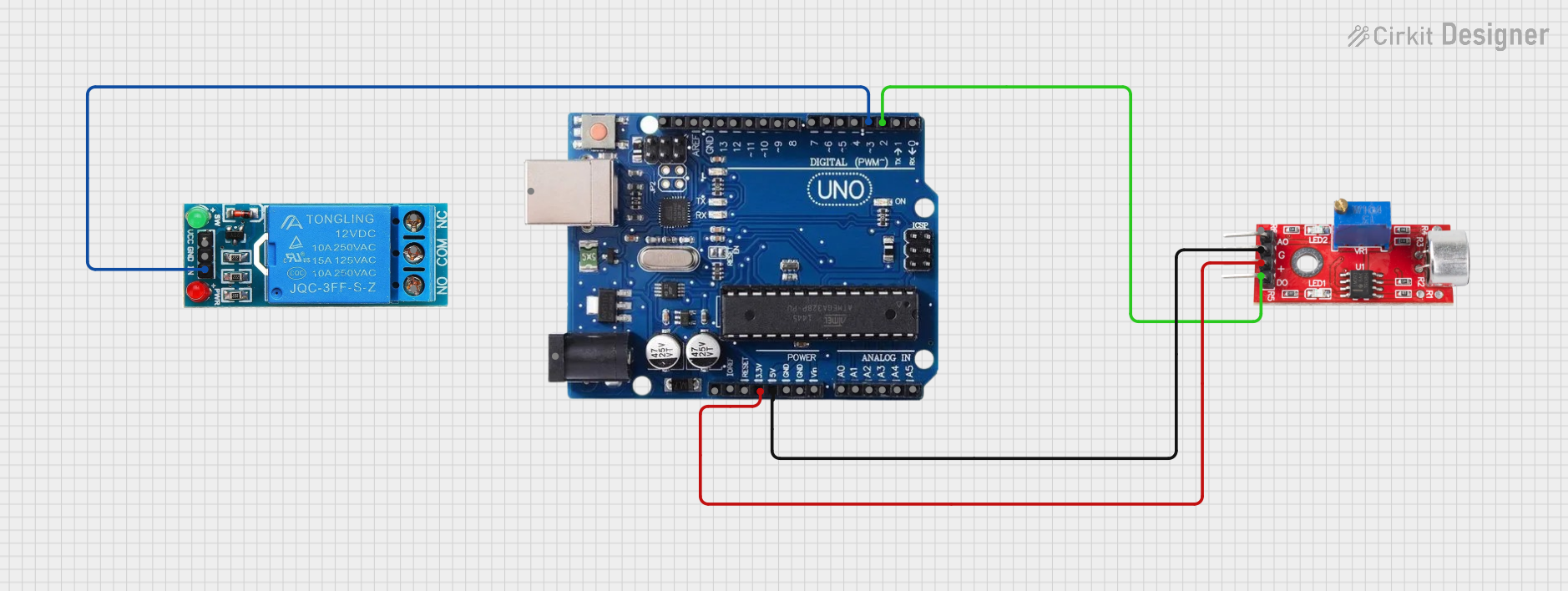
Circuit Documentation
Summary
This circuit is designed to control a water sink system using an Arduino Uno R3 microcontroller, a sound sensor, and a 12V single-channel relay. The system activates the water flow when a specific sound command, presumably "nyalakan air," is detected by the sound sensor. The sound sensor's digital output is connected to the Arduino, which in turn controls the relay to manage the water flow.
Component List
Sound Sensor
- Pins: Analog, GND, VCC, Digital
- Description: A sensor that detects sound levels and provides both analog and digital outputs. In this circuit, the digital output is used to trigger an action when a certain sound level is detected.
Arduino Uno R3
- Pins: USB Port, Power Jack, Not Connected, IOREF, RESET, 3.3V, 5V, GND, VIN, A0-A5, SCL, SDA, AREF, Digital Pins 0-13
- Description: A microcontroller board based on the ATmega328P. It has 14 digital input/output pins, 6 analog inputs, a USB connection, a power jack, an ICSP header, and a reset button.
12V Single Channel Relay
- Pins: NC, COM, NO, IN, GND, VCC
- Description: An electromechanical switch that allows a low-power circuit to control a high-power circuit. It has a normally closed (NC), common (COM), and normally open (NO) terminal for switching, as well as an input (IN), ground (GND), and power (VCC) terminal.
Wiring Details
Sound Sensor
- Analog: Not connected in this circuit.
- GND: Connected to the GND pin on the Arduino Uno R3.
- VCC: Connected to the 5V pin on the Arduino Uno R3.
- Digital: Connected to digital pin 2 on the Arduino Uno R3.
Arduino Uno R3
- GND: Connected to the GND pin on the Sound Sensor and the GND pin on the 12V Single Channel Relay.
- 5V: Connected to the VCC pin on the Sound Sensor.
- Digital Pin 2: Connected to the Digital pin on the Sound Sensor.
- Digital Pin 3: Connected to the IN pin on the 12V Single Channel Relay.
12V Single Channel Relay
- NC: Not connected in this circuit.
- COM: Not connected in this circuit.
- NO: Not connected in this circuit.
- IN: Connected to digital pin 3 on the Arduino Uno R3.
- GND: Connected to the GND pin on the Arduino Uno R3.
- VCC: Not connected in this circuit.
Documented Code
Sound Sensor Code (Arduino Uno R3)
/*
 * This Arduino sketch is designed for a water sink system. The system turns on
 * the water when it hears the command 'nyalakan air'. The sound sensor is
 * connected to the Arduino, and the relay controlling the water flow is also
 * connected to the Arduino. The sound sensor's digital output is connected to
 * pin 2 of the Arduino, and the relay's input is connected to pin 3 of the
 * Arduino.
 */

const int soundSensorPin = 2; // Pin connected to the sound sensor's digital out
const int relayPin = 3;       // Pin connected to the relay's input

void setup() {
  pinMode(soundSensorPin, INPUT); // Set sound sensor pin as input
  pinMode(relayPin, OUTPUT);      // Set relay pin as output
  digitalWrite(relayPin, LOW);    // Ensure relay is off initially
}

void loop() {
  int soundState = digitalRead(soundSensorPin); // Read sound sensor state
  if (soundState == HIGH) { // If sound sensor detects sound
    digitalWrite(relayPin, HIGH); // Turn on the relay (water on)
  } else {
    digitalWrite(relayPin, LOW);  // Turn off the relay (water off)
  }
}
Arduino Uno R3 Default Code
void setup() {
  // put your setup code here, to run once:

}

void loop() {
  // put your main code here, to run repeatedly:

}
(Note: The default code for the Arduino Uno R3 does not perform any specific function and is provided for completeness. The actual functionality is implemented in the Sound Sensor Code section.)