
Raspberry Pi 4B-Based Smart Surveillance System with GPS and Ultrasonic Sensing
View and Edit Project In Cirkit Designer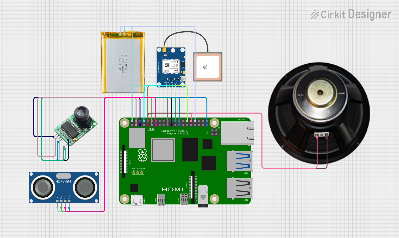
Circuit Documentation
Summary
The circuit in question is designed to interface a Raspberry Pi 4B with several peripheral devices, including an Arducam camera module, an HC-SR04 ultrasonic sensor, a GPS NEO 6M module, and a speaker. The circuit is powered by a 2000mAh battery. The Raspberry Pi 4B serves as the central processing unit, controlling the peripherals and processing data from the sensors. The Arducam is connected via I2C and SPI interfaces, the GPS module communicates through serial communication, and the ultrasonic sensor is interfaced using GPIO pins for trigger and echo signals. The speaker is driven by a GPIO pin for audio output.
Component List
Raspberry Pi 4B
- A single-board computer with a variety of digital GPIO pins, power supply pins, and communication interfaces.
- Utilized for controlling the peripherals and processing sensor data.
Arducam
- A camera module compatible with Raspberry Pi, interfaced via I2C and SPI.
- Used for capturing images or video data.
HC-SR04 Ultrasonic Sensor
- A sensor that measures distance using ultrasonic waves.
- Connected to the Raspberry Pi for distance measurement tasks.
Speaker
- An audio output device.
- Driven by the Raspberry Pi to produce sound signals.
GPS NEO 6M
- A GPS module for receiving satellite navigation data.
- Provides location data to the Raspberry Pi.
2000mAh Battery
- A power source for the circuit.
- Supplies power to the Raspberry Pi and the connected peripherals.
Wiring Details
Raspberry Pi 4B
- 5V connected to Arducam (+5V), GPS NEO 6M (VCC), HC-SR04 Ultrasonic Sensor (VCC), and 2000mAh Battery (VCC).
- GND connected to Arducam (GND), HC-SR04 Ultrasonic Sensor (GND), GPS NEO 6M (GND), Speaker (-), and 2000mAh Battery (GND).
- GPIO2 (SDA) connected to Arducam (SDA).
- GPIO3 (SCL) connected to Arducam (SCL).
- GPIO14 (TXD) connected to GPS NEO 6M (RX).
- GPIO15 (RXD) connected to GPS NEO 6M (TX).
- GPIO17 connected to HC-SR04 Ultrasonic Sensor (TRIG).
- GPIO27 connected to HC-SR04 Ultrasonic Sensor (ECHO).
- GPIO10 (MOSI) connected to Arducam (MOSI).
- GPIO9 (MISO) connected to Arducam (MISO).
- GPIO8 (CE0) connected to Arducam (CS).
- GPIO12 connected to Speaker (+).
Arducam
- +5V connected to Raspberry Pi 4B (5V).
- GND connected to Raspberry Pi 4B (GND).
- SCL connected to Raspberry Pi 4B (GPIO3).
- SDA connected to Raspberry Pi 4B (GPIO2).
- MOSI connected to Raspberry Pi 4B (GPIO10).
- MISO connected to Raspberry Pi 4B (GPIO9).
- CS connected to Raspberry Pi 4B (GPIO8).
HC-SR04 Ultrasonic Sensor
- VCC connected to Raspberry Pi 4B (5V).
- GND connected to Raspberry Pi 4B (GND).
- TRIG connected to Raspberry Pi 4B (GPIO17).
- ECHO connected to Raspberry Pi 4B (GPIO27).
Speaker
- + connected to Raspberry Pi 4B (GPIO12).
- - connected to Raspberry Pi 4B (GND).
GPS NEO 6M
- VCC connected to Raspberry Pi 4B (5V).
- GND connected to Raspberry Pi 4B (GND).
- RX connected to Raspberry Pi 4B (GPIO14).
- TX connected to Raspberry Pi 4B (GPIO15).
2000mAh Battery
- VCC connected to Raspberry Pi 4B (5V).
- GND connected to Raspberry Pi 4B (GND).
Documented Code
No code has been provided for the microcontrollers in the circuit. Therefore, this section is currently empty. When code is available, it should be documented here with appropriate descriptions of its functionality and usage.