
Arduino UNO Based Environmental Monitoring System with Servo Control and Rain Detection
View and Edit Project In Cirkit Designer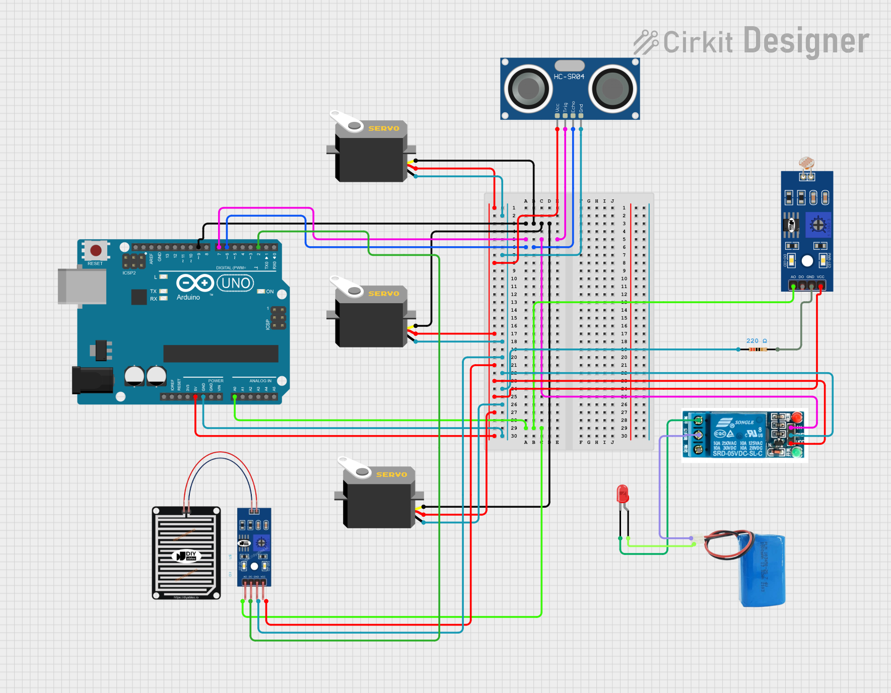
Circuit Documentation
Summary
This circuit is designed to interface various sensors and actuators with an Arduino UNO microcontroller. The circuit includes input devices such as a rain sensor and an LDR (Light Dependent Resistor), and output devices including servos, an ultrasonic sensor, a relay, and an LED. The Arduino UNO serves as the central processing unit, reading sensor inputs and controlling the output devices based on the programmed logic. The circuit is powered by a 5V battery, and a resistor is used to protect the LED from excessive current.
Component List
Arduino UNO
- Microcontroller board based on the ATmega328P
- Features digital I/O pins, analog input pins, and power supply pins
Rain Sensor
- Detects rainwater and provides analog and digital outputs
Resistor (220 Ohms)
- Limits current to prevent damage to components such as LEDs
Servos (x3)
- Rotary actuators that can be positioned to specific angular positions using PWM signals
LED: Two Pin (red)
- Emits red light when powered
- Requires current limiting via a resistor
HC-SR04 Ultrasonic Sensor
- Measures distance by emitting ultrasonic waves and timing their return
LDR (Light Dependent Resistor)
- Changes resistance based on the intensity of light it receives
5V Relay
- Electrically operated switch that can control a circuit by a low-power signal
5V Battery
- Provides power to the circuit
Wiring Details
Arduino UNO
- Digital Pin 9 (D9) connected to Servo pulse pins
- Digital Pin 7 (D7) connected to HC-SR04 Ultrasonic Sensor TRIG pin
- Digital Pin 6 (D6) connected to HC-SR04 Ultrasonic Sensor ECHO pin
- Analog Pin 0 (A0) connected to LDR A0 pin and Rain Sensor AO pin
- Digital Pin 2 (D2) connected to Rain Sensor DO pin
- 5V pin connected to VCC pins of Servo, HC-SR04 Ultrasonic Sensor, Rain Sensor, 5V Relay, and LDR
- GND pin connected to GND pins of Servo, HC-SR04 Ultrasonic Sensor, Rain Sensor, 5V Relay, and Resistor pin1
Rain Sensor
- AO pin connected to Arduino UNO Analog Pin 0 (A0)
- DO pin connected to Arduino UNO Digital Pin 2 (D2)
- VCC pin connected to Arduino UNO 5V pin
- GRD pin connected to common ground
Resistor (220 Ohms)
- Pin1 connected to common ground
- Pin2 connected to LDR GND pin
Servos (x3)
- Pulse pins connected to Arduino UNO Digital Pin 9 (D9)
- VCC pins connected to Arduino UNO 5V pin
- GND pins connected to common ground
LED: Two Pin (red)
- Cathode connected to 5V Relay Normally Open pin
- Anode connected to 5V Battery negative terminal
HC-SR04 Ultrasonic Sensor
- TRIG pin connected to Arduino UNO Digital Pin 7 (D7)
- ECHO pin connected to Arduino UNO Digital Pin 6 (D6)
- VCC pin connected to Arduino UNO 5V pin
- GND pin connected to common ground
LDR (Light Dependent Resistor)
- A0 pin connected to Arduino UNO Analog Pin 0 (A0)
- GND pin connected to Resistor pin2
- VCC pin connected to Arduino UNO 5V pin
5V Relay
- In pin connected to HC-SR04 Ultrasonic Sensor TRIG pin
- VCC pin connected to Arduino UNO 5V pin
- GND pin connected to common ground
- Normally Open pin connected to LED cathode
- Common terminal connected to 5V Battery positive terminal
5V Battery
- Positive terminal connected to 5V Relay Common terminal
- Negative terminal connected to LED anode
Documented Code
Arduino UNO Code (sketch.ino)
void setup() {
  // put your setup code here, to run once:

}

void loop() {
  // put your main code here, to run repeatedly:

}
Additional Notes (documentation.txt)
No additional code documentation provided.