
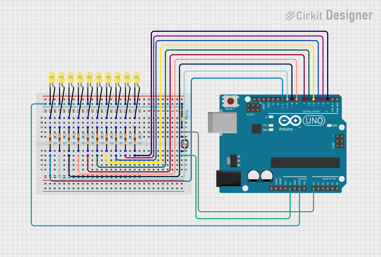
Circuit Documentation
Summary
This circuit is designed to control 10 yellow LEDs based on the light intensity measured by a Light Dependent Resistor (LDR). The LDR is connected to the analog input A0 of an Arduino UNO, and the LEDs are connected to digital pins D2 through D11. The brightness of the LEDs is adjusted according to the light intensity detected by the LDR.
Component List
Arduino UNO
- Description: A microcontroller board based on the ATmega328P.
- Pins: UNUSED, IOREF, Reset, 3.3V, 5V, GND, Vin, A0, A1, A2, A3, A4, A5, SCL, SDA, AREF, D13, D12, D11, D10, D9, D8, D7, D6, D5, D4, D3, D2, D1, D0
LED: Two Pin (yellow)
- Description: A yellow LED with two pins: anode and cathode.
- Pins: cathode, anode
Resistor
- Description: A resistor with a resistance of 330 Ohms.
- Pins: pin1, pin2
- Properties:
- Resistance: 330 Ohms
Photocell (LDR)
- Description: A Light Dependent Resistor (LDR) that changes its resistance based on the light intensity.
- Pins: pin 0, pin 1
Wiring Details
Arduino UNO
A0 is connected to:
- pin 0 of the Photocell (LDR)
- pin2 of a Resistor
5V is connected to:
- pin 1 of the Photocell (LDR)
D2 is connected to:
- pin2 of a Resistor
D3 is connected to:
- pin2 of a Resistor
D4 is connected to:
- pin2 of a Resistor
D5 is connected to:
- pin2 of a Resistor
D6 is connected to:
- pin2 of a Resistor
D7 is connected to:
- pin2 of a Resistor
D8 is connected to:
- pin2 of a Resistor
D9 is connected to:
- pin2 of a Resistor
D10 is connected to:
- pin2 of a Resistor
D11 is connected to:
- pin2 of a Resistor
GND is connected to:
- cathode of all LEDs
LED: Two Pin (yellow)
anode of each LED is connected to:
- pin1 of a Resistor
cathode of each LED is connected to:
- GND of the Arduino UNO
Resistor
pin1 of each Resistor is connected to:
- anode of an LED
pin2 of each Resistor is connected to:
- D2 through D11 of the Arduino UNO (one pin per digital pin)
Photocell (LDR)
pin 0 is connected to:
- A0 of the Arduino UNO
- pin2 of a Resistor
pin 1 is connected to:
- 5V of the Arduino UNO
Code Documentation
/*
 * This Arduino sketch controls 10 yellow LEDs based on the light intensity
 * measured by a Light Dependent Resistor (LDR). The LDR is connected to the
 * analog input A0, and the LEDs are connected to digital pins D2 through D11.
 */

const int ldrPin = A0; // LDR connected to analog pin A0
const int ledPins[] = {2, 3, 4, 5, 6, 7, 8, 9, 10, 11}; // LED pins

void setup() {
  // Initialize LED pins as outputs
  for (int i = 0; i < 10; i++) {
    pinMode(ledPins[i], OUTPUT);
  }
}

void loop() {
  int ldrValue = analogRead(ldrPin); // Read the LDR value
  int brightness = map(ldrValue, 0, 1023, 0, 255); // Map LDR value to brightness

  // Set the brightness of each LED
  for (int i = 0; i < 10; i++) {
    analogWrite(ledPins[i], brightness);
  }

  delay(100); // Small delay to stabilize readings
}
This code reads the value from the LDR connected to analog pin A0, maps the value to a brightness level, and sets the brightness of the 10 LEDs connected to digital pins D2 through D11 accordingly. The setup function initializes the LED pins as outputs, and the loop function continuously reads the LDR value, maps it to a brightness level, and updates the LEDs.