
Arduino UNO-Based Multi-Color LED Display with Joystick Control and LCD Interface
View and Edit Project In Cirkit Designer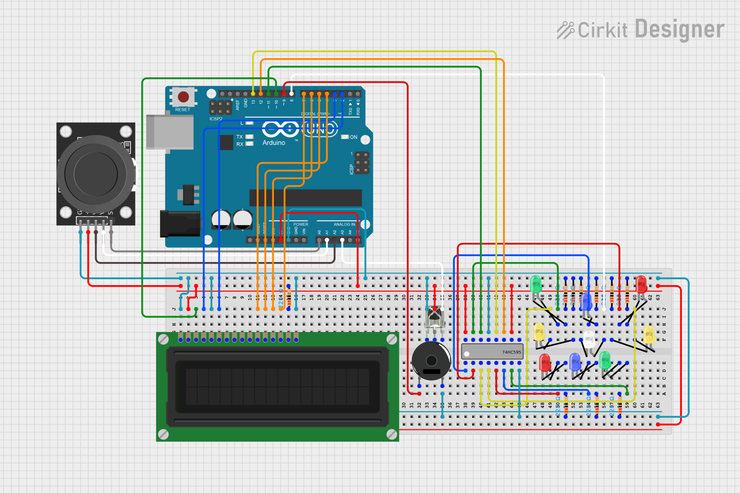
Circuit Documentation
Summary
This circuit involves an Arduino UNO microcontroller interfacing with various components including an LCD display, a 74HC595 shift register, multiple LEDs of different colors, resistors, a joystick module, an IR receiver, and a piezo buzzer. The circuit is designed to demonstrate basic input and output operations, including displaying information on an LCD, controlling LEDs, and reading inputs from a joystick and an IR receiver.
Component List
KY-023 Dual Axis Joystick Module
- Pins: GND, +5V, VRx, VRy, SW
- Description: A joystick module that provides analog output for X and Y axes and a digital output for the switch.
74HC595
- Pins: Q1, Q2, Q3, Q4, Q5, Q6, Q7, GND, VCC, Q0, DS (DATA), OE (Enable), ST_CP (RCLK), SH_CP (SRCLK), MR (SRCLR), Q7' (QH)
- Description: A serial-in, parallel-out shift register used to control multiple LEDs.
Resistor
- Pins: pin1, pin2
- Description: Resistors with a resistance of 220 Ohms used for current limiting.
LED: Two Pin (yellow)
- Pins: cathode, anode
- Description: A yellow LED.
LCD Display (16 pin)
- Pins: VSS, VDD, VO, RS, R_W, E, DB0, DB1, DB2, DB3, DB4, DB5, DB6, DB7, A, K
- Description: A 16-pin LCD display used for displaying text.
LED: Two Pin (red)
- Pins: cathode, anode
- Description: A red LED.
LED: Two Pin (white)
- Pins: cathode, anode
- Description: A white LED.
LED: Two Pin (blue)
- Pins: cathode, anode
- Description: A blue LED.
LED: Two Pin (green)
- Pins: cathode, anode
- Description: A green LED.
VS1838B IR Receiver
- Pins: OUT, GND, VCC
- Description: An IR receiver module.
Piezo Buzzer
- Pins: pin 1, pin 2
- Description: A piezo buzzer for sound output.
Arduino UNO
- Pins: UNUSED, IOREF, Reset, 3.3V, 5V, GND, Vin, A0, A1, A2, A3, A4, A5, SCL, SDA, AREF, D13, D12, D11, D10, D9, D8, D7, D6, D5, D4, D3, D2, D1, D0
- Description: A microcontroller board based on the ATmega328P.
Wiring Details
KY-023 Dual Axis Joystick Module
- GND connected to GND of Arduino UNO.
- +5V connected to 5V of Arduino UNO.
- VRx connected to A2 of Arduino UNO.
- VRy connected to A1 of Arduino UNO.
- SW connected to A0 of Arduino UNO.
74HC595
- GND connected to GND of Arduino UNO.
- VCC connected to 5V of Arduino UNO.
- OE (Enable) connected to GND.
- MR (SRCLR) connected to 5V.
- DS (DATA) connected to D11 of Arduino UNO.
- ST_CP (RCLK) connected to D13 of Arduino UNO.
- SH_CP (SRCLK) connected to D12 of Arduino UNO.
- Q0 connected to anode of green LED.
- Q1 connected to anode of blue LED.
- Q2 connected to anode of red LED.
- Q3 connected to anode of yellow LED.
- Q4 connected to anode of yellow LED.
- Q5 connected to anode of red LED.
- Q6 connected to anode of blue LED.
- Q7 connected to anode of green LED.
Resistors
- pin1 of each resistor connected to the cathode of corresponding LEDs.
- pin2 of each resistor connected to GND.
LCD Display (16 pin)
- VSS connected to GND.
- VDD connected to 5V.
- VO connected to D10 of Arduino UNO.
- RS connected to D2 of Arduino UNO.
- R_W connected to GND.
- E connected to D3 of Arduino UNO.
- DB4 connected to D4 of Arduino UNO.
- DB5 connected to D5 of Arduino UNO.
- DB6 connected to D6 of Arduino UNO.
- DB7 connected to D7 of Arduino UNO.
- A connected to pin1 of a resistor.
- K connected to GND.
VS1838B IR Receiver
- OUT connected to GND.
- GND connected to GND.
- VCC connected to A3 of Arduino UNO.
Piezo Buzzer
- pin 1 connected to D9 of Arduino UNO.
- pin 2 connected to GND.
LEDs
- Yellow LED:
- anode connected to Q3 and Q4 of 74HC595.
- cathode connected to pin1 of a resistor.
- Red LED:
- anode connected to Q2 and Q5 of 74HC595.
- cathode connected to pin1 of a resistor.
- White LED:
- anode connected to D8 of Arduino UNO.
- cathode connected to pin1 of a resistor.
- Blue LED:
- anode connected to Q1 and Q6 of 74HC595.
- cathode connected to pin1 of a resistor.
- Green LED:
- anode connected to Q0 and Q7 of 74HC595.
- cathode connected to pin1 of a resistor.
Documented Code
Arduino UNO Code (sketch.ino)
void setup() {
  // put your setup code here, to run once:

}

void loop() {
  // put your main code here, to run repeatedly:

}
Additional Documentation (documentation.txt)
This documentation provides a comprehensive overview of the circuit, including a detailed list of components, their wiring connections, and the code used in the Arduino UNO microcontroller.