
Wi-Fi Controlled Smart Lighting System with ESP8266 and Relay Module
View and Edit Project In Cirkit Designer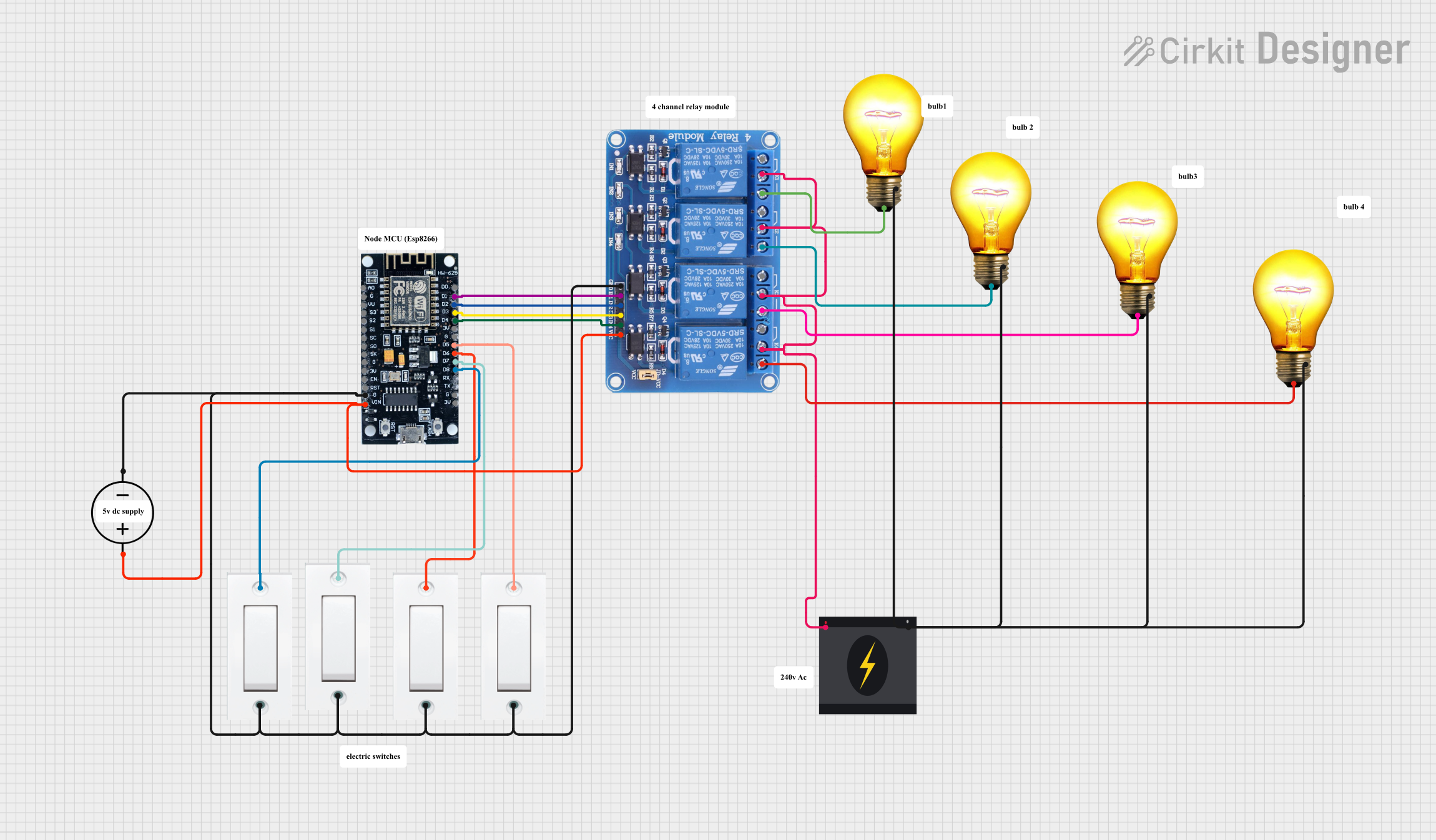
Circuit Documentation
Summary
This circuit involves an ESP8266 microcontroller, a 4-channel relay module, multiple flush switches, AC bulbs, and power sources. The ESP8266 controls the relay module, which in turn controls the AC bulbs. The flush switches are used to provide input to the ESP8266. The circuit is powered by both a DC power source and a 240V AC power source.
Component List
ESP8266
- Description: A Wi-Fi microcontroller used for controlling the relay module.
- Pins: 3V, G, D8, D7, D6, D5, D4, D3, D2, D1, D0, A0, S3, S2, S1, SC, S0, SK, EN, VIN, RST, VU
Flush Switch
- Description: A switch used to provide input to the ESP8266.
- Pins: GND, VCC
240V Power Source
- Description: Provides 240V AC power to the circuit.
- Pins: Live, Neutral
AC Bulb
- Description: An AC bulb controlled by the relay module.
- Pins: P, N
Relay 4 Channel 5V
- Description: A relay module used to control the AC bulbs.
- Pins: GND, IN1, IN2, IN3, IN4, VCC, COM1, COM2, COM3, COM4, NO1, NO2, NO3, NO4, NC1, NC2, NC3, NC4
DC Power Source
- Description: Provides DC power to the circuit.
- Pins: Ground, Positive
Wiring Details
ESP8266
G is connected to:
- GND of Relay 4 Channel 5V
- GND of all Flush Switches
- Ground of DC Power Source
D1 is connected to IN1 of Relay 4 Channel 5V
D2 is connected to IN2 of Relay 4 Channel 5V
D3 is connected to IN3 of Relay 4 Channel 5V
D4 is connected to IN4 of Relay 4 Channel 5V
VIN is connected to:
- VCC of Relay 4 Channel 5V
- Positive of DC Power Source
D8 is connected to VCC of one Flush Switch
D7 is connected to VCC of another Flush Switch
D6 is connected to VCC of another Flush Switch
D5 is connected to VCC of another Flush Switch
Flush Switch
GND is connected to:
- G of ESP8266
- GND of Relay 4 Channel 5V
- Ground of DC Power Source
VCC is connected to:
- D8 of ESP8266 (one switch)
- D7 of ESP8266 (another switch)
- D6 of ESP8266 (another switch)
- D5 of ESP8266 (another switch)
240V Power Source
Live is connected to COM1, COM2, COM3, and COM4 of Relay 4 Channel 5V
Neutral is connected to:
- N of all AC Bulbs
AC Bulb
P is connected to:
- NO1 of Relay 4 Channel 5V (one bulb)
- NO2 of Relay 4 Channel 5V (another bulb)
- NO3 of Relay 4 Channel 5V (another bulb)
- NO4 of Relay 4 Channel 5V (another bulb)
N is connected to Neutral of 240V Power Source
Relay 4 Channel 5V
GND is connected to:
- G of ESP8266
- GND of all Flush Switches
- Ground of DC Power Source
IN1 is connected to D1 of ESP8266
IN2 is connected to D2 of ESP8266
IN3 is connected to D3 of ESP8266
IN4 is connected to D4 of ESP8266
VCC is connected to:
- VIN of ESP8266
- Positive of DC Power Source
COM1 is connected to Live of 240V Power Source
COM2 is connected to Live of 240V Power Source
COM3 is connected to Live of 240V Power Source
COM4 is connected to Live of 240V Power Source
NO1 is connected to P of one AC Bulb
NO2 is connected to P of another AC Bulb
NO3 is connected to P of another AC Bulb
NO4 is connected to P of another AC Bulb
DC Power Source
Ground is connected to:
- G of ESP8266
- GND of Relay 4 Channel 5V
- GND of all Flush Switches
Positive is connected to:
- VIN of ESP8266
- VCC of Relay 4 Channel 5V
Code
No code is provided for this circuit.