
Circuit Documentation
Summary
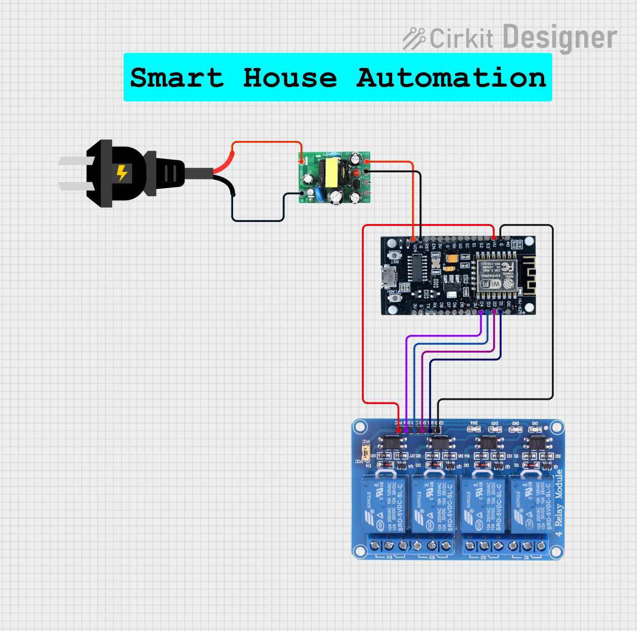
This document provides a detailed overview of a circuit that includes an ESP8266 microcontroller, a 4-channel relay module, an AC to DC converter, and an AC power source. The ESP8266 controls the relay module, which in turn can control various AC loads. The AC to DC converter provides the necessary DC power for the ESP8266 and the relay module.
Component List
ESP8266
- Description: A Wi-Fi enabled microcontroller used for IoT applications.
- Pins: 3V, G, D8, D7, D6, D5, D4, D3, D2, D1, D0, A0, S3, S2, S1, SC, S0, SK, EN, VIN, RST, VU
Relay 4 Channel 5v
- Description: A relay module that allows control of high voltage devices using low voltage signals.
- Pins: GND, IN1, IN2, IN3, IN4, VCC, COM1, COM2, COM3, COM4, NO1, NO2, NO3, NO4, NC1, NC2, NC3, NC4
AC to DC Converter
- Description: Converts AC power to DC power.
- Pins: 12v, -, 5v, live, neutral
AC Source
- Description: Provides AC power to the circuit.
- Pins: +, -
Comment
- Description: Placeholder for comments or notes.
- Pins: None
Wiring Details
ESP8266
- D4 is connected to IN4 of the Relay 4 Channel 5v.
- D3 is connected to IN3 of the Relay 4 Channel 5v.
- D2 is connected to IN2 of the Relay 4 Channel 5v.
- D1 is connected to IN1 of the Relay 4 Channel 5v.
- G is connected to GND of the Relay 4 Channel 5v.
- G is also connected to - of the AC to DC Converter.
- VIN is connected to 12v of the AC to DC Converter.
- VU is connected to VCC of the Relay 4 Channel 5v.
Relay 4 Channel 5v
- IN4 is connected to D4 of the ESP8266.
- IN3 is connected to D3 of the ESP8266.
- IN2 is connected to D2 of the ESP8266.
- IN1 is connected to D1 of the ESP8266.
- GND is connected to G of the ESP8266.
- VCC is connected to VU of the ESP8266.
AC to DC Converter
- - is connected to G of the ESP8266.
- 12v is connected to VIN of the ESP8266.
- live is connected to + of the AC Source.
- neutral is connected to - of the AC Source.
AC Source
- + is connected to live of the AC to DC Converter.
- - is connected to neutral of the AC to DC Converter.
Code
No code is provided for this circuit.