
ESP32-Based Weather Monitoring System with Rain and Light Sensing
View and Edit Project In Cirkit Designer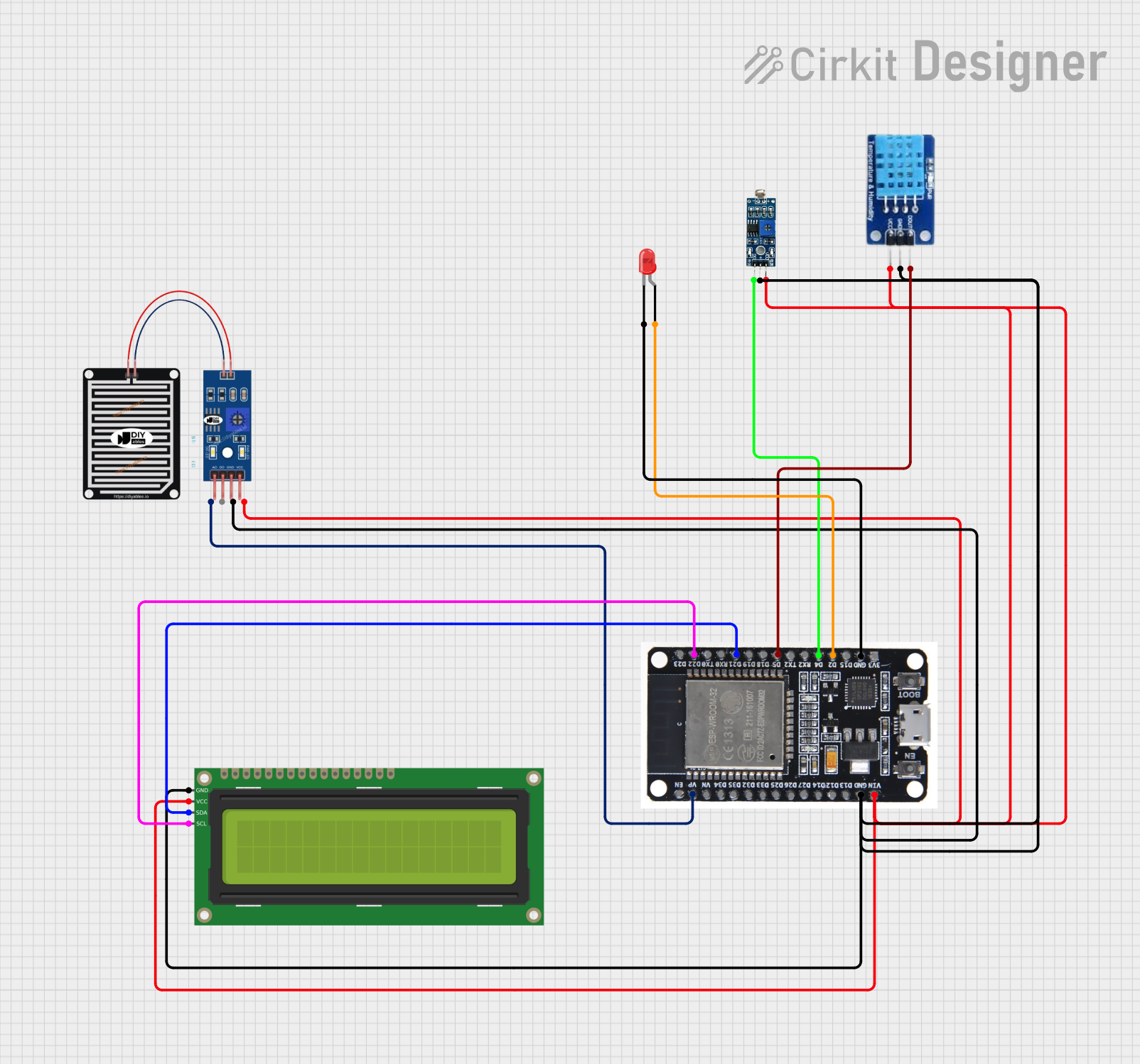
Circuit Documentation
Summary of the Circuit
This circuit is designed to interface a variety of sensors and an LED with an ESP32 microcontroller. The sensors include a rain sensor, an LDR (Light Dependent Resistor) module, and a DHT11 temperature and humidity sensor. Additionally, the circuit features a 16x2 I2C LCD for display purposes. The ESP32 microcontroller serves as the central processing unit, reading sensor data and controlling the LED based on the sensor inputs. The rain sensor and LDR module provide analog and digital outputs, respectively, which are read by the ESP32. The DHT11 communicates with the ESP32 via a single data line. The LED is controlled by a digital output from the ESP32. Power distribution is managed through common VCC and GND lines.
Component List
RAIN SENSOR
- Pins: AO, DO, GRD, VCC
- Description: A sensor that detects rainwater presence by measuring the resistance between two electrodes.
ESP32
- Pins: EN, VP, VN, D34, D35, D32, D33, D25, D26, D27, D14, D12, D13, GND, VIN, 3V3, D15, D2, D4, RX2, TX2, D5, D18, D19, D21, RX0, TX0, D22, D23, BOOT
- Description: A microcontroller with Wi-Fi and Bluetooth capabilities, featuring a wide range of GPIO pins for interfacing with various peripherals.
16x2 I2C LCD
- Pins: GND, VCC, SDA, SCL
- Description: A liquid crystal display that can show 16 characters per line for 2 lines, interfaced via the I2C protocol.
LDR Module 3 pin
- Pins: VCC, GND, DO
- Description: A light sensor module that outputs a digital signal based on the intensity of ambient light.
DHT11
- Pins: DATA, GND, VCC
- Description: A sensor that measures ambient temperature and humidity, providing a digital output.
LED: Two Pin (red)
- Pins: cathode, anode
- Description: A basic red LED for indicating status or events.
Wiring Details
RAIN SENSOR
- AO connected to ESP32 VP
- DO not connected
- GRD connected to common GND
- VCC connected to common VCC
ESP32
- GND connected to common GND
- VIN connected to common VCC
- VP connected to RAIN SENSOR AO
- D2 connected to LED anode
- D4 connected to LDR Module DO
- D5 connected to DHT11 DATA
- D21 connected to 16x2 I2C LCD SDA
- D22 connected to 16x2 I2C LCD SCL
- Other pins not used in this circuit
16x2 I2C LCD
- GND connected to common GND
- VCC connected to common VCC
- SDA connected to ESP32 D21
- SCL connected to ESP32 D22
LDR Module 3 pin
- VCC connected to common VCC
- GND connected to common GND
- DO connected to ESP32 D4
DHT11
- DATA connected to ESP32 D5
- GND connected to common GND
- VCC connected to common VCC
LED: Two Pin (red)
- cathode connected to common GND
- anode connected to ESP32 D2
Documented Code
No code was provided for the microcontroller. Typically, the code would be documented here, including setup routines, main loop, and any interrupt service routines or additional functions. The code would handle initializing the peripherals, reading sensor data, controlling the LED, and updating the display on the 16x2 I2C LCD.