
Arduino UNO-Based Smart Environmental Monitoring System with OLED Display and Battery-Powered Fan
View and Edit Project In Cirkit Designer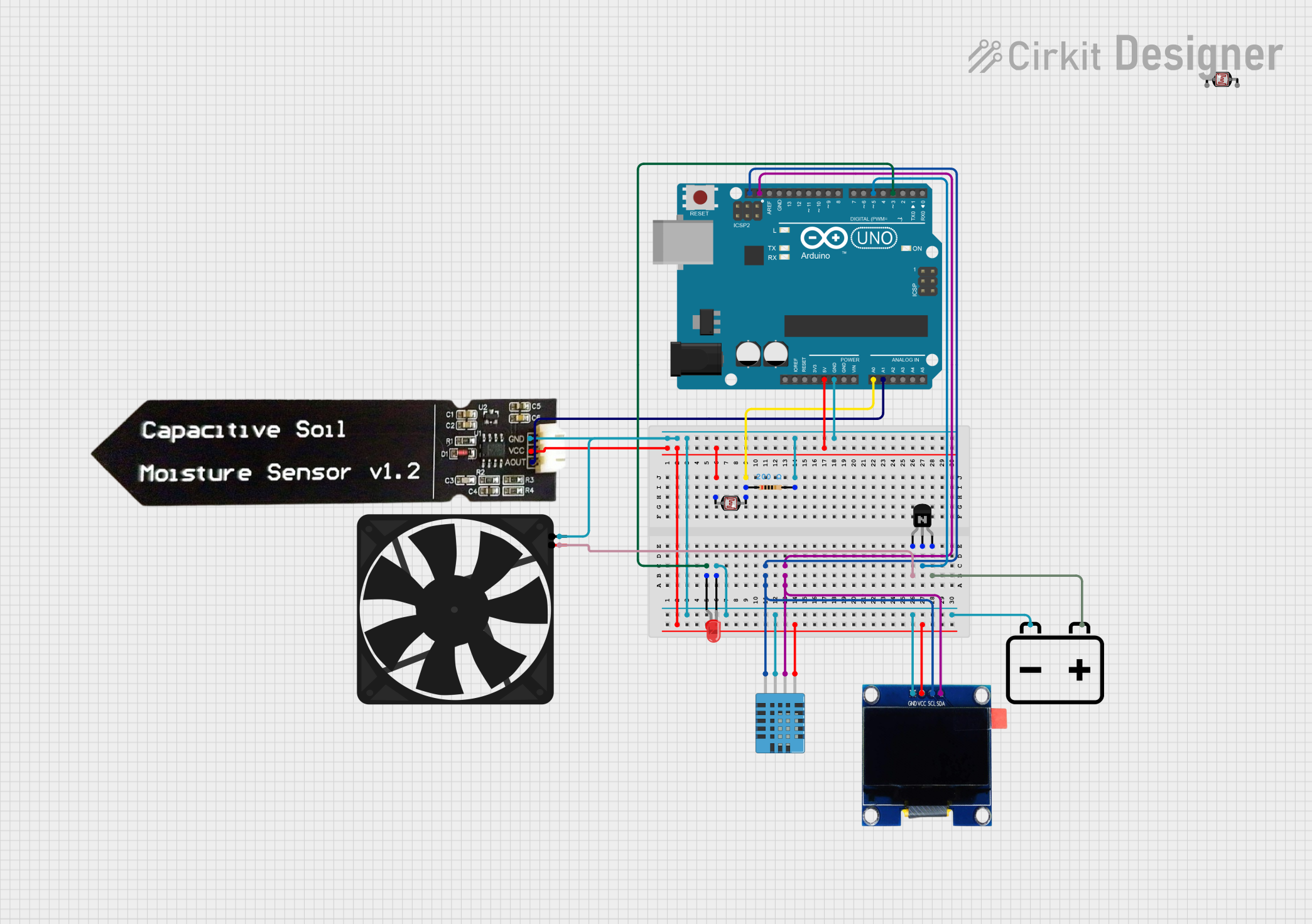
Circuit Documentation
Summary
This circuit integrates an Arduino UNO microcontroller with various sensors and output devices to monitor environmental conditions and control a fan. The sensors include a humidity and temperature sensor, a capacitive soil moisture sensor, and a photocell (LDR). An OLED display is used to show the sensor readings, and an LED indicates the system status. A fan is controlled via an NPN transistor, which is powered by a 12V battery.
Component List
Arduino UNO
- Description: Microcontroller board based on the ATmega328P.
- Pins: UNUSED, IOREF, Reset, 3.3V, 5V, GND, Vin, A0, A1, A2, A3, A4, A5, SCL, SDA, AREF, D13, D12, D11, D10, D9, D8, D7, D6, D5, D4, D3, D2, D1, D0
AM2320 Humidity and Temperature Sensor
- Description: Digital temperature and humidity sensor.
- Pins: Vin, SDA, GND, SCL
OLED 1.3" Display
- Description: 1.3-inch OLED display for visual output.
- Pins: GND, VCC, SCL, SDA
Capacitive Soil Moisture Sensor V1.2
- Description: Sensor to measure soil moisture levels.
- Pins: GND, VCC, AOUT
Resistor
- Description: 200 Ohms resistor.
- Pins: pin1, pin2
Photocell (LDR)
- Description: Light-dependent resistor to measure light intensity.
- Pins: pin 0, pin 1
LED: Two Pin (red)
- Description: Red LED for status indication.
- Pins: cathode, anode
Fan
- Description: Small fan for air circulation.
- Pins: GND, 5V
NPN Transistor (EBC)
- Description: NPN transistor for switching applications.
- Pins: emitter, base, collector
12V Battery
- Description: Power source for the fan.
- Pins: -, +
Wiring Details
Arduino UNO
- D3: Connected to the anode of the LED.
- GND: Connected to the GND pins of the AM2320 sensor, OLED display, 12V battery, resistor, capacitive soil moisture sensor, fan.
- 5V: Connected to the VCC pins of the capacitive soil moisture sensor, AM2320 sensor, OLED display.
- A0: Connected to pin 0 of the photocell (LDR) through a resistor.
- A1: Connected to the AOUT pin of the capacitive soil moisture sensor.
- SCL: Connected to the SCL pins of the AM2320 sensor and OLED display.
- SDA: Connected to the SDA pins of the AM2320 sensor and OLED display.
- D5: Connected to the base of the NPN transistor.
AM2320 Humidity and Temperature Sensor
- Vin: Connected to the 5V pin of the Arduino UNO.
- SDA: Connected to the SDA pin of the Arduino UNO.
- GND: Connected to the GND pin of the Arduino UNO.
- SCL: Connected to the SCL pin of the Arduino UNO.
OLED 1.3" Display
- GND: Connected to the GND pin of the Arduino UNO.
- VCC: Connected to the 5V pin of the Arduino UNO.
- SCL: Connected to the SCL pin of the Arduino UNO.
- SDA: Connected to the SDA pin of the Arduino UNO.
Capacitive Soil Moisture Sensor V1.2
- GND: Connected to the GND pin of the Arduino UNO.
- VCC: Connected to the 5V pin of the Arduino UNO.
- AOUT: Connected to the A1 pin of the Arduino UNO.
Resistor
- pin1: Connected to pin 0 of the photocell (LDR).
- pin2: Connected to the GND pin of the Arduino UNO.
Photocell (LDR)
- pin 0: Connected to pin1 of the resistor.
- pin 1: Connected to the 5V pin of the Arduino UNO.
LED: Two Pin (red)
- anode: Connected to the D3 pin of the Arduino UNO.
- cathode: Connected to the GND pin of the Arduino UNO.
Fan
- GND: Connected to the GND pin of the Arduino UNO.
- 5V: Connected to the emitter of the NPN transistor.
NPN Transistor (EBC)
- emitter: Connected to the 5V pin of the fan.
- base: Connected to the D5 pin of the Arduino UNO.
- collector: Connected to the + pin of the 12V battery.
12V Battery
- -: Connected to the GND pin of the Arduino UNO.
- +: Connected to the collector of the NPN transistor.
Documented Code
Arduino UNO Code (sketch.ino)
void setup() {
  // put your setup code here, to run once:

}

void loop() {
  // put your main code here, to run repeatedly:

}
Additional Documentation (documentation.txt)