ESP32-Based Infrared Proximity Sensing System

Circuit Documentation
Summary of the Circuit
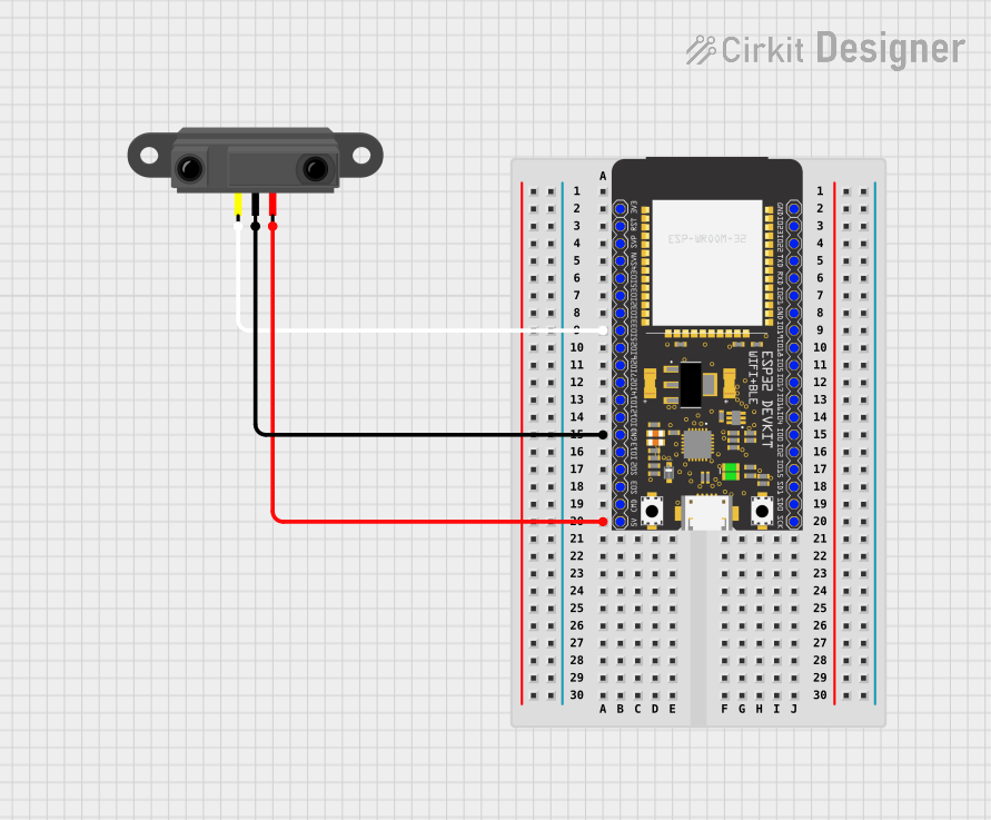
This circuit consists of an ESP32 Wroom microcontroller unit (MCU) and an Infrared Proximity Sensor. The ESP32 Wroom is a powerful MCU with Wi-Fi and Bluetooth capabilities, which can be used for a variety of IoT applications. The Infrared Proximity Sensor is used to detect the presence of objects or motion within its range. The sensor's output is connected to one of the GPIO pins of the ESP32, allowing the MCU to read the proximity data. The ground and power supply pins of both components are interconnected to complete the circuit.
Component List
ESP32 Wroom
- Description: A microcontroller with Wi-Fi and Bluetooth capabilities, suitable for a wide range of IoT applications.
- Pins:
- 3V3
- Reset
- GPIO36
- GPIO39
- GPIO34
- GPIO35
- GPIO32
- GPIO33
- GPIO25
- GPIO26
- GPIO27
- GPIO14
- GPIO12
- GND
- GPIO13
- GPIO9
- GPIO10
- GPIO11
- 5V
- GPIO23
- GPIO22/SCL
- GPIO1/TXD0
- GPIO3/RXD0
- GPIO21/SDA
- GPIO19
- GPIO18
- GPIO5
- GPIO17
- GPIO16
- GPIO4
- GPIO0
- GPIO2
- GPIO15
- GPIO8
- GPIO7
- GPIO6
Infrared Proximity Sensor
- Description: A sensor that detects the presence of objects or motion within its range by emitting infrared light.
- Pins:
- Vout
- GND
- Vcc
Wiring Details
ESP32 Wroom
- GPIO33: Connected to the Vout pin of the Infrared Proximity Sensor.
- GND: Connected to the GND pin of the Infrared Proximity Sensor.
- 5V: Connected to the Vcc pin of the Infrared Proximity Sensor.
Infrared Proximity Sensor
- Vout: Connected to GPIO33 of the ESP32 Wroom.
- GND: Connected to the GND pin of the ESP32 Wroom.
- Vcc: Connected to the 5V pin of the ESP32 Wroom.
Documented Code
No code has been provided for the microcontroller. Typically, the code would be used to initialize the GPIO pins, set up communication protocols, and implement the logic for reading the sensor data and responding to it. Since there is no code provided, this section cannot be documented further. If code becomes available, it should be added here with appropriate comments and explanations for each function and routine.