Arduino Mega 2560-Controlled Stepper Motors with RFID Access and Traffic Light Indication
Circuit Documentation
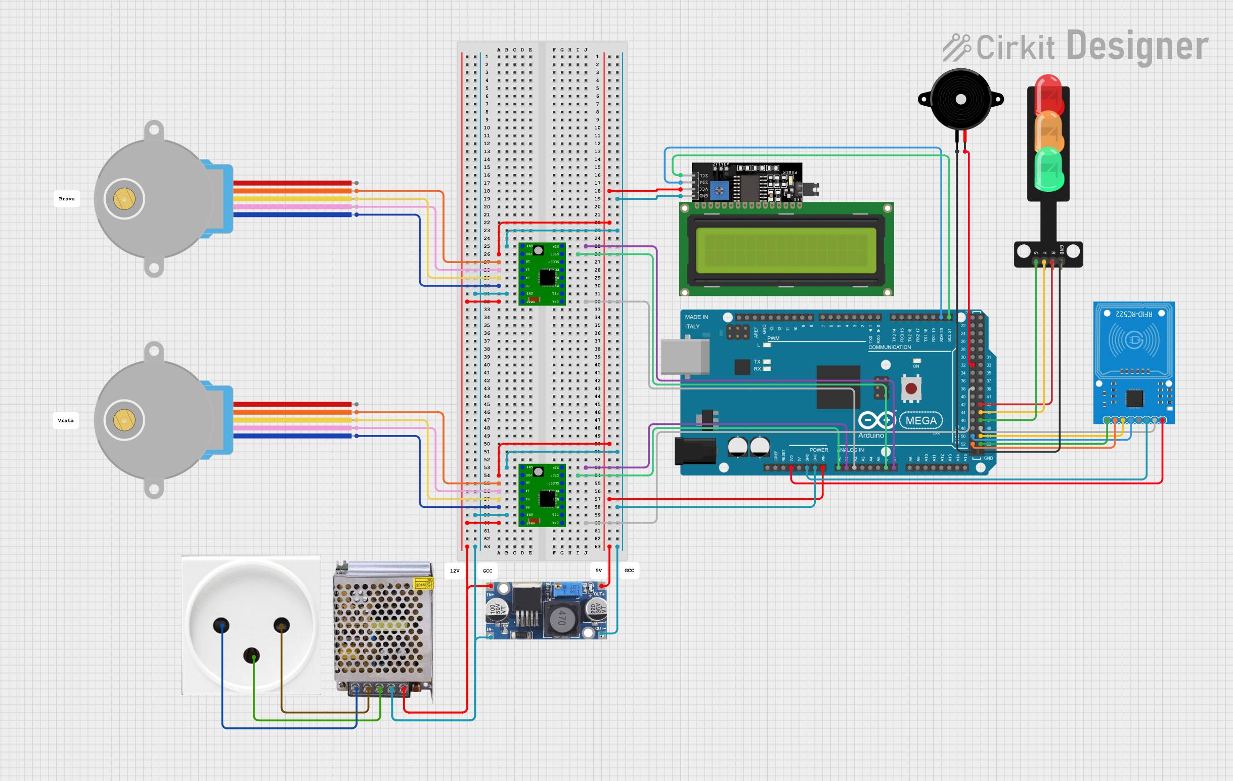
Summary
This circuit is designed to control two 28BYJ-48 Stepper Motors using A4988 Stepper Motor Driver Carriers, interfaced with an Arduino Mega 2560 microcontroller. The circuit also includes an LCD Display 16x4 I2C for user interface, an RFID-RC522 module for RFID reading, a Piezo Speaker for audio feedback, and a Traffic Light module for visual signaling. The power supply is a 12V 5A unit, and a 48V to 5V converter is used to step down the voltage for certain components. The circuit is connected to a power outlet for AC power input.
Component List
- 28BYJ-48 Stepper Motor: A unipolar stepper motor with a 5-wire interface.
- POWER SUPPLY 12V 5AMP: Provides DC power to the circuit from an AC source.
- Power Outlet (IL): The interface for AC power input.
- Traffic Light: A module with Green, Yellow, and Red LEDs to simulate a traffic light.
- Piezo Speaker: An electronic device that can produce sound when an electrical signal is applied.
- LCD Display 16x4 I2C: A 16x4 character LCD display with an I2C interface.
- RFID-RC522: An RFID reader/writer module.
- 48V to 5V Converter: Steps down voltage from 48V to 5V.
- Arduino Mega 2560: A microcontroller board based on the ATmega2560.
- A4988 Stepper Motor Driver Carrier: A module that drives stepper motors.
Wiring Details
28BYJ-48 Stepper Motor
- BLUE, PINK, YELLOW, ORANGE: Connected to the corresponding pins on the A4988 Stepper Motor Driver Carrier.
- RED: Not connected in the provided net list.
POWER SUPPLY 12V 5AMP
- 220V Positive Pole (AC), 220V Negative Pole (AC): Connected to the corresponding poles of the power outlet.
- GND (DC): Common ground with the A4988 Stepper Motor Driver Carriers and the 48V to 5V converter.
- 12V-24V Output (DC): Supplies power to the A4988 Stepper Motor Driver Carriers and the 48V to 5V converter.
Power Outlet (IL)
- N, L, GND: Connected to the corresponding pins on the POWER SUPPLY 12V 5AMP.
Traffic Light
- Green, Yellow, Red: Controlled by the Arduino Mega 2560.
- GND: Common ground with the Arduino Mega 2560.
Piezo Speaker
- Pin1: Connected to the ground on the Arduino Mega 2560.
- Pin2: Controlled by the Arduino Mega 2560.
LCD Display 16x4 I2C
- SCL, SDA: Connected to the corresponding I2C pins on the Arduino Mega 2560.
- VCC: Powered by the 48V to 5V converter.
- GND: Common ground with the Arduino Mega 2560.
RFID-RC522
- SDA, SCK, MOSI, MISO, IRQ, RST: Connected to the corresponding pins on the Arduino Mega 2560.
- 3.3V: Powered by the 3.3V output from the Arduino Mega 2560.
- GND: Common ground with the Arduino Mega 2560.
48V to 5V Converter
- Out+: Supplies 5V to the LCD Display 16x4 I2C.
- Out--: Common ground with the A4988 Stepper Motor Driver Carriers and the POWER SUPPLY 12V 5AMP.
- In+: Receives 12V-24V from the POWER SUPPLY 12V 5AMP.
- In--: Common ground with the POWER SUPPLY 12V 5AMP.
Arduino Mega 2560
- Various I/O Pins: Connected to the A4988 Stepper Motor Driver Carriers, LCD Display 16x4 I2C, RFID-RC522, Piezo Speaker, and Traffic Light as per the net list.
- GND, VIN, 3V3: Provide power and ground connections to various components.
A4988 Stepper Motor Driver Carrier
- ENABLE, MS1, MS2, MS3, RESET, SLEEP, STEP, DIR: Controlled by the Arduino Mega 2560.
- GND, VCC: Power connections from the 48V to 5V converter and common ground.
- 1B, 1A, 2A, 2B: Connected to the corresponding pins on the 28BYJ-48 Stepper Motors.
- VMOT: Receives motor power from the POWER SUPPLY 12V 5AMP.
Documented Code
void setup() {
  // put your setup code here, to run once:

}

void loop() {
  // put your main code here, to run repeatedly:

}
The provided code is a template with empty setup() and loop() functions, which are the entry points for Arduino sketches. The setup() function is called once when the sketch starts and is used for initializing settings or pin modes. The loop() function is called repeatedly and contains the main logic of the sketch. Additional code would be required to control the components as per the wiring details.