
ESP32-CAM Controlled Robot with L298N Motor Driver and Servo Actuation
View and Edit Project In Cirkit Designer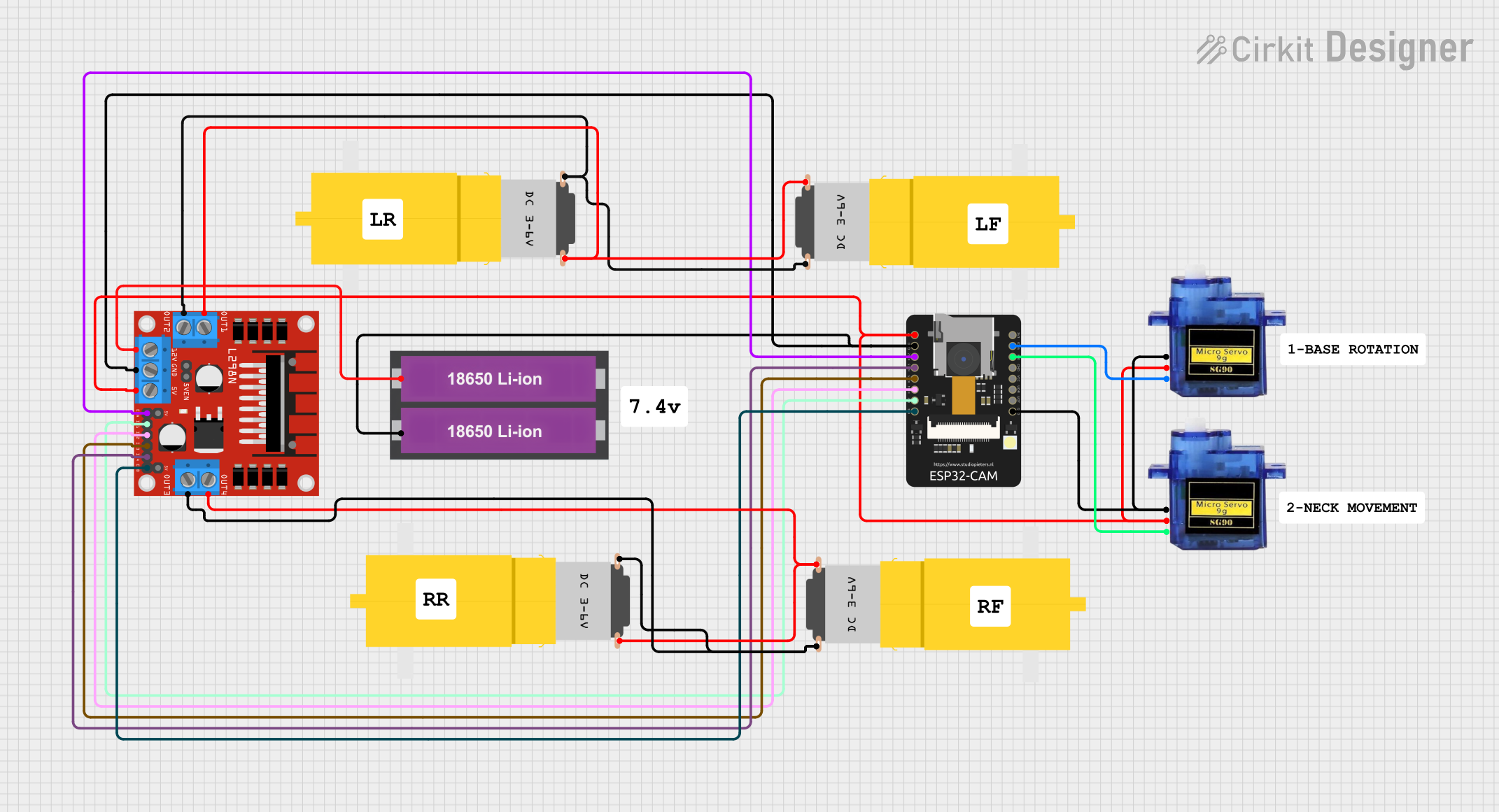
Circuit Documentation
Summary
This circuit is designed to control two sets of DC motors using an L298N DC motor driver, which is interfaced with an ESP32-CAM microcontroller. The ESP32-CAM provides control signals to the motor driver for manipulating the speed and direction of the motors. Additionally, the circuit includes two micro servos that are controlled by the ESP32-CAM. Power is supplied by a pair of 18650 Li-ion batteries connected to the motor driver, which also distributes power to the microcontroller and servos.
Component List
L298N DC Motor Driver
- Description: A module capable of driving two DC motors with control over speed and direction.
- Pins: OUT1, OUT2, 12V, GND, 5V, OUT3, OUT4, 5V-ENA-JMP-I, 5V-ENA-JMP-O, +5V-J1, +5V-J2, ENA, IN1, IN2, IN3, IN4, ENB
ESP32 - CAM
- Description: A microcontroller module with Wi-Fi capability, often used for IoT projects and equipped with a camera interface.
- Pins: 5V, GND, IO12, IO13, IO15, IO14, IO2, IO4, VOT, VOR, VCC, IO0, IO16, 3V3
18650 Li-ion Battery x 2
- Description: A power source consisting of two lithium-ion cells in series or parallel to provide the required operating voltage.
- Pins: +, -
Motor Amarillo Motorreductor Hobby (4 instances)
- Description: A yellow hobby gear motor used for simple mechanical motion tasks.
- Pins: vcc, GND
Micro Servo 9G (2 instances)
- Description: A small and lightweight servo motor suitable for applications requiring simple position control.
- Pins: GND, +5V, PWM
Comments (7 instances)
- Description: Placeholder components for annotations or notes within the circuit design, not physical parts.
Wiring Details
L298N DC Motor Driver
- OUT1, OUT2 connected to one set of Motor Amarillo motorreductor hobby (vcc, GND)
- OUT3, OUT4 connected to another set of Motor Amarillo motorreductor hobby (vcc, GND)
- 12V connected to 18650 Li-ion Battery (+)
- GND connected to 18650 Li-ion Battery (-) and ESP32 - CAM (GND)
- 5V connected to ESP32 - CAM (5V) and Micro Servo 9G (+5V)
- ENA connected to ESP32 - CAM (IO12)
- IN1 connected to ESP32 - CAM (IO2)
- IN2 connected to ESP32 - CAM (IO14)
- IN3 connected to ESP32 - CAM (IO15)
- IN4 connected to ESP32 - CAM (IO13)
- ENB connected to ESP32 - CAM (IO4)
ESP32 - CAM
- 5V connected to L298N DC Motor Driver (5V)
- GND connected to L298N DC Motor Driver (GND) and Micro Servo 9G (GND)
- IO12 connected to L298N DC Motor Driver (ENA)
- IO2 connected to L298N DC Motor Driver (IN1)
- IO14 connected to L298N DC Motor Driver (IN2)
- IO15 connected to L298N DC Motor Driver (IN3)
- IO13 connected to L298N DC Motor Driver (IN4)
- IO4 connected to L298N DC Motor Driver (ENB)
- IO0 connected to Micro Servo 9G (PWM)
- IO16 connected to Micro Servo 9G (PWM)
18650 Li-ion Battery x 2
-
- connected to L298N DC Motor Driver (12V)
-
- connected to L298N DC Motor Driver (GND)
Motor Amarillo Motorreductor Hobby
- Four instances, each with vcc and GND connected to corresponding OUT pins on the L298N DC Motor Driver.
Micro Servo 9G
- Two instances, each with +5V connected to L298N DC Motor Driver (5V), GND connected to ESP32 - CAM (GND), and PWM connected to ESP32 - CAM (IO0 or IO16).
Documented Code
There is no code provided for the microcontrollers in the circuit. The ESP32 - CAM would typically be programmed to control the L298N DC motor driver and the micro servos based on some input or sensor data. The code would include initialization of the GPIO pins, setup of PWM channels for motor and servo control, and logic for handling control signals to achieve the desired motion. Since no code is available, this section cannot be completed.