Cirkit Designer
Your all-in-one circuit design IDE
Home /
Project Documentation
Arduino UNO Based Sound-Activated LCD Message Display

Circuit Documentation
Summary of the Circuit
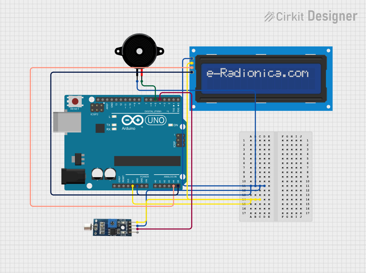
This circuit is designed around an Arduino UNO microcontroller, which serves as the central processing unit. The circuit includes an LCD screen with an I2C interface for display purposes, a piezo speaker for audio output, and a sound sensor for audio input. The Arduino UNO manages the interactions between these components, processing the input from the sound sensor and controlling the output to the LCD screen and the piezo speaker.
Component List
Arduino UNO
- Description: A microcontroller board based on the ATmega328P.
- Pins: UNUSED, IOREF, Reset, 3.3V, 5V, GND, Vin, A0-A5, SCL, SDA, AREF, D0-D13.
- Purpose: Acts as the central processing unit of the circuit, interfacing with sensors, controlling the LCD screen, and driving the piezo speaker.
LCD screen 16x2 I2C
- Description: A 16x2 character LCD display with an I2C communication interface.
- Pins: SCL, SDA, VCC, GND.
- Purpose: Displays information processed by the Arduino UNO.
Piezo Speaker
- Description: An electronic component that can produce sound when an electrical signal is applied.
- Pins: pin1, pin2.
- Purpose: Outputs audio signals under the control of the Arduino UNO.
Sound Sensor
- Description: A sensor that detects sound and converts it into an electrical signal.
- Pins: VCC, GND, DO, AO.
- Purpose: Captures audio signals and sends them to the Arduino UNO for processing.
Wiring Details
Arduino UNO
- 5V connected to VCC of LCD screen and Sound Sensor.
- GND connected to GND of LCD screen, Piezo Speaker, and Sound Sensor.
- A4 (SDA) connected to SDA of LCD screen.
- A5 (SCL) connected to SCL of LCD screen.
- D4 connected to DO of Sound Sensor.
- D5 connected to pin2 of Piezo Speaker.
LCD screen 16x2 I2C
- VCC connected to 5V of Arduino UNO.
- GND connected to GND of Arduino UNO.
- SDA connected to A4 (SDA) of Arduino UNO.
- SCL connected to A5 (SCL) of Arduino UNO.
Piezo Speaker
- pin1 connected to GND of Arduino UNO.
- pin2 connected to D5 of Arduino UNO.
Sound Sensor
- VCC connected to 5V of Arduino UNO.
- GND connected to GND of Arduino UNO.
- DO connected to D4 of Arduino UNO.
Documented Code
Arduino UNO Code (sketch.ino)
void setup() {
  // put your setup code here, to run once:

}

void loop() {
  // put your main code here, to run repeatedly:

}
Note: The provided code is a template and does not include specific functionality. It should be populated with the setup and loop code required to control the LCD screen, read from the sound sensor, and drive the piezo speaker.