
ESP32-Based Sensor Monitoring System with OLED Display and E-Stop
View and Edit Project In Cirkit Designer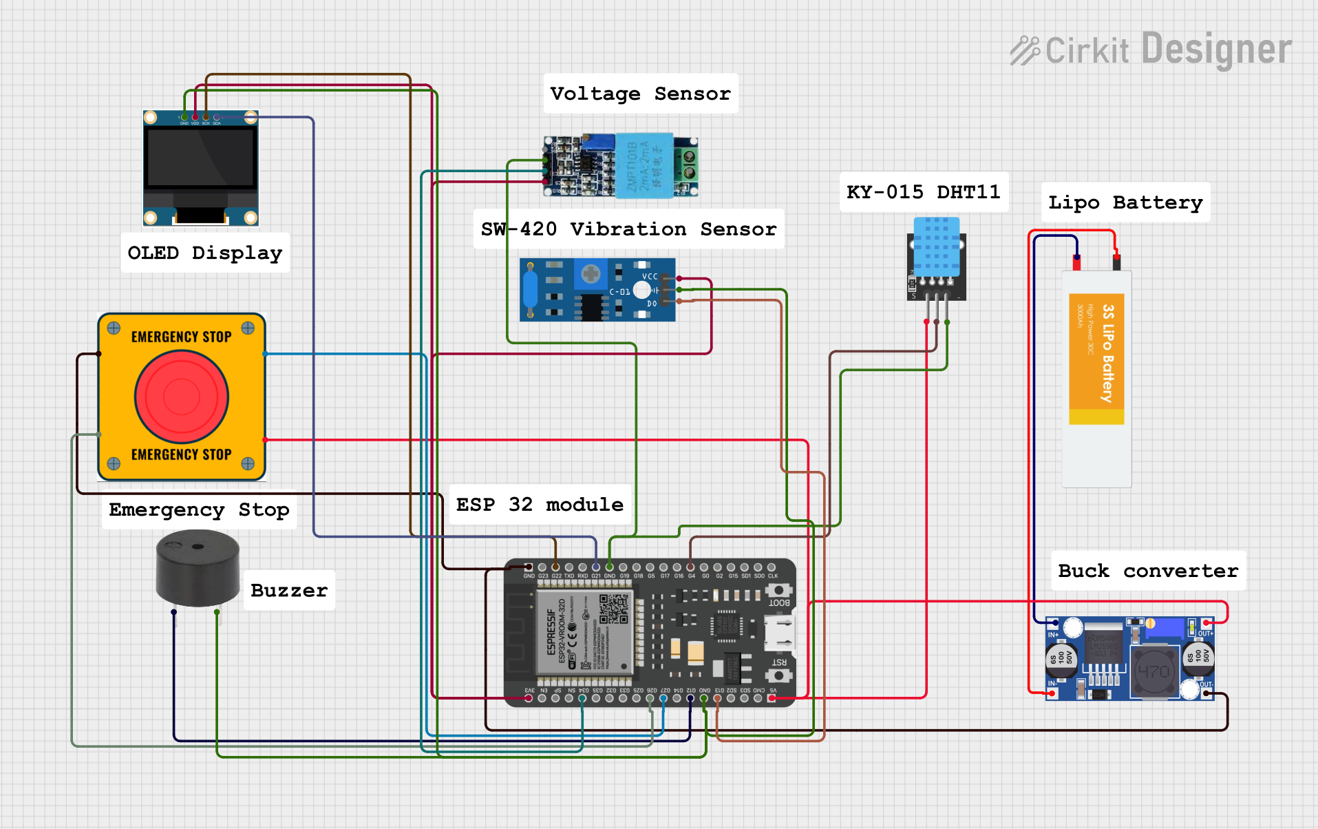
Circuit Documentation
Summary
The circuit in question appears to be a microcontroller-based system with various sensors and output devices. The core of the circuit is an ESP32 microcontroller, which is powered by a Lipo Battery through a Buck Converter to step down the voltage. The ESP32 interfaces with a DHT11 temperature and humidity sensor, a SW-420 vibration sensor, a voltage sensor, and an OLED display for user interface. An emergency stop (E Stop) is included for safety, and a buzzer provides audible feedback. The circuit is designed to monitor environmental parameters and provide visual and audible outputs based on sensor readings and user interactions.
Component List
Lipo Battery
- Description: A rechargeable battery that provides power to the circuit.
- Pins: VCC, GND
ESP32 - 38 pins
- Description: A microcontroller with Wi-Fi and Bluetooth capabilities.
- Pins: 3V3, EN, SP, SN, G34, G35, G32, G33, G25, G26, G27, G14, G12, GND, G13, SD2, SD3, CMD, 5V, G23, G22, TXD, RXD, G21, G19, G18, G5, G17, G16, G4, G0, G2, G15, SD1, SD0, CLK
Buck Converter
- Description: A DC-DC converter that steps down voltage from the battery to a lower level suitable for the microcontroller and other components.
- Pins: IN+, IN-, OUT+, OUT-
Buzzer
- Description: An audible signaling device.
- Pins: PIN, GND
E Stop
- Description: An emergency stop switch for safety purposes.
- Pins: NO 1, NO 2, NC 1, NC 2
KY-015 DHT11
- Description: A temperature and humidity sensor module.
- Pins: 5V, S, GND
SW-420 Vibration Sensor
- Description: A module that detects vibrations.
- Pins: vcc, Ground, Digital output
Voltage Sensor
- Description: A sensor that measures the voltage in a circuit.
- Pins: Ground, Phase, Vcc, Out, Gnd
0.96" OLED
- Description: A small OLED display for visual output.
- Pins: GND, VDD, SCK, SDA
Wiring Details
Lipo Battery
- VCC connected to Buck Converter IN+
- GND connected to Buck Converter IN-
ESP32 - 38 pins
- 3V3 connected to OLED VDD, Voltage Sensor Vcc, SW-420 Vibration Sensor vcc
- GND connected to OLED GND, Buzzer GND, SW-420 Vibration Sensor Ground, Voltage Sensor Gnd, KY-015 DHT11 GND
- G34 connected to Voltage Sensor Out
- G26 connected to E Stop NC 1
- G27 connected to E Stop NO 2
- G12 connected to Buzzer PIN
- G13 connected to SW-420 Vibration Sensor Digital output
- 5V connected to KY-015 DHT11 5V, E Stop NC 2, Buck Converter OUT+
- G4 connected to KY-015 DHT11 S
- G22 connected to OLED SCK
- G21 connected to OLED SDA
Buck Converter
- IN+ connected to Lipo Battery VCC
- IN- connected to Lipo Battery GND
- OUT+ connected to ESP32 5V
- OUT- connected to ESP32 GND
Buzzer
- PIN connected to ESP32 G12
- GND connected to ESP32 GND
E Stop
- NC 1 connected to ESP32 G26
- NO 2 connected to ESP32 G27
- NC 2 connected to ESP32 5V
- NO 1 connected to ESP32 GND
KY-015 DHT11
- 5V connected to ESP32 5V
- S connected to ESP32 G4
- GND connected to ESP32 GND
SW-420 Vibration Sensor
- vcc connected to ESP32 3V3
- Ground connected to ESP32 GND
- Digital output connected to ESP32 G13
Voltage Sensor
- Vcc connected to ESP32 3V3
- Out connected to ESP32 G34
- Gnd connected to ESP32 GND
0.96" OLED
- GND connected to ESP32 GND
- VDD connected to ESP32 3V3
- SCK connected to ESP32 G22
- SDA connected to ESP32 G21
Documented Code
No code was provided for the microcontroller. Typically, the code would be documented here, including setup routines, main loop, and any interrupt service routines or function definitions. The code would be responsible for initializing the peripherals, reading sensor data, processing inputs, driving the display, and handling any communication protocols.