
Arduino Mega 2560-Based Smart Sensor System with IR Sensors, LCD Display, and Stepper Motor Control
View and Edit Project In Cirkit Designer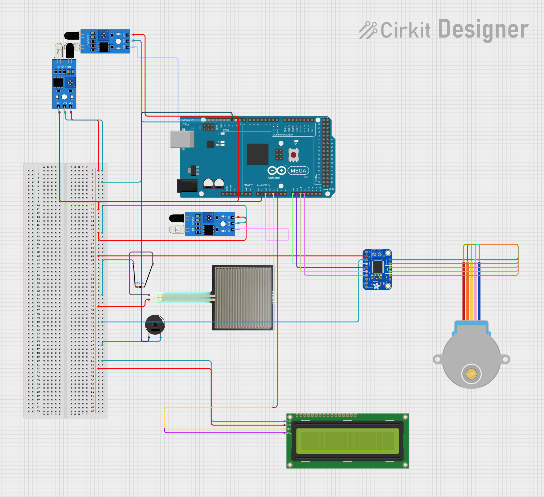
Circuit Documentation
Summary
This document provides a detailed overview of a circuit that includes an Arduino Mega 2560 microcontroller, multiple IR sensors, a 16x2 I2C LCD, a Square FSR, a resistor, a piezo buzzer, a stepper motor, and a motor driver. The circuit is designed to interface various sensors and actuators with the Arduino Mega 2560, allowing for a range of functionalities.
Component List
Arduino Mega 2560
- Description: A microcontroller board based on the ATmega2560.
- Pins: IOREF, RESET, 3V3, 5V, GND, VIN, A0-A15, D0-D53, AREF, SDA, SCL
IR Sensor
- Description: Infrared sensor for detecting objects.
- Pins: out, gnd, vcc
16x2 I2C LCD
- Description: A 16x2 character LCD with I2C interface.
- Pins: GND, VCC, SDA, SCL
Square FSR
- Description: Force-sensitive resistor.
- Pins: A0, A1
Resistor
- Description: 200 Ohms resistor.
- Pins: pin1, pin2
- Properties: Resistance: 200 Ohms
Piezo Buzzer
- Description: A piezoelectric buzzer for sound output.
- Pins: pin 1, pin 2
28BYJ-48 Stepper Motor
- Description: A 5V stepper motor.
- Pins: BLUE, PINK, YELLOW, ORANGE, RED
Adafruit TB6612 DC and Stepper Motor Driver
- Description: Motor driver for controlling DC and stepper motors.
- Pins: PWRIN, VCC, GND, PWMB, BIN2, BIN1, STBY, AIN1, AIN2, PWMA, MOTORA1, MOTORA2, MOTORB2, MOTORB1, Vmotor
Wiring Details
Arduino Mega 2560
- 5V: Connected to VCC of IR sensors, Adafruit TB6612 motor driver, Square FSR, and 16x2 I2C LCD.
- GND: Connected to GND of IR sensors, Adafruit TB6612 motor driver, Resistor, Piezo Buzzer, and 16x2 I2C LCD.
- A1: Connected to out of IR sensor.
- A2: Connected to out of IR sensor.
- A4: Connected to SDA of 16x2 I2C LCD.
- A5: Connected to SCL of 16x2 I2C LCD.
- A8: Connected to PWMB of Adafruit TB6612 motor driver.
- A9: Connected to BIN2 of Adafruit TB6612 motor driver.
- A10: Connected to BIN1 of Adafruit TB6612 motor driver.
- A11: Connected to STBY of Adafruit TB6612 motor driver.
- D10 PWM: Connected to out of IR sensor.
- D11 PWM: Connected to pin 1 of Piezo Buzzer.
IR Sensor
- vcc: Connected to 5V of Arduino Mega 2560.
- gnd: Connected to GND of Arduino Mega 2560.
- out: Connected to A1, A2, and D10 PWM of Arduino Mega 2560.
16x2 I2C LCD
- VCC: Connected to 5V of Arduino Mega 2560.
- GND: Connected to GND of Arduino Mega 2560.
- SDA: Connected to A4 of Arduino Mega 2560.
- SCL: Connected to A5 of Arduino Mega 2560.
Square FSR
- A0: Connected to pin2 of Resistor.
- A1: Connected to 5V of Arduino Mega 2560.
Resistor
- pin1: Connected to GND of Arduino Mega 2560.
- pin2: Connected to A0 of Square FSR.
Piezo Buzzer
- pin 1: Connected to D11 PWM of Arduino Mega 2560.
- pin 2: Connected to GND of Arduino Mega 2560.
28BYJ-48 Stepper Motor
- BLUE: Connected to MOTORA2 of Adafruit TB6612 motor driver.
- PINK: Connected to GND of Adafruit TB6612 motor driver.
- YELLOW: Connected to GND of Adafruit TB6612 motor driver.
- ORANGE: Connected to MOTORB1 of Adafruit TB6612 motor driver.
- RED: Connected to MOTORB2 of Adafruit TB6612 motor driver.
Adafruit TB6612 DC and Stepper Motor Driver
- VCC: Connected to 5V of Arduino Mega 2560.
- GND: Connected to GND of Arduino Mega 2560.
- PWMB: Connected to A8 of Arduino Mega 2560.
- BIN2: Connected to A9 of Arduino Mega 2560.
- BIN1: Connected to A10 of Arduino Mega 2560.
- STBY: Connected to A11 of Arduino Mega 2560.
- MOTORA2: Connected to BLUE of 28BYJ-48 Stepper Motor.
- MOTORB1: Connected to ORANGE of 28BYJ-48 Stepper Motor.
- MOTORB2: Connected to RED of 28BYJ-48 Stepper Motor.
Documented Code
Arduino Mega 2560 Code
void setup() {
  // put your setup code here, to run once:

}

void loop() {
  // put your main code here, to run repeatedly:

}
Additional Documentation
This document provides a comprehensive overview of the circuit, including a summary, component list, wiring details, and documented code.