Cirkit Designer
Your all-in-one circuit design IDE
Home /
Project Documentation
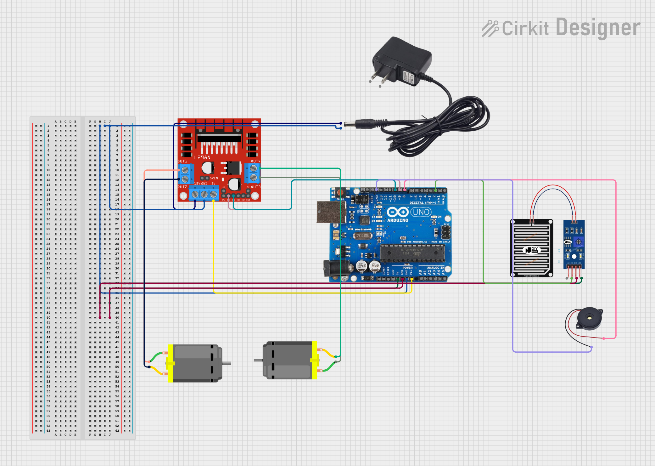
Arduino Uno Automated Rain-Sensing Roof with L298N Motor Driver
Circuit Documentation
Summary
This circuit is designed to automatically close a roof when rain is detected and open it when the rain stops. The system uses an Arduino Uno R3 microcontroller to read input from a rain sensor and control a DC motor via an L298N motor driver. Additionally, a buzzer is used to provide audible feedback during the roof's operation.
Component List
L298N DC Motor Driver
- Description: A dual H-Bridge motor driver that allows control of the speed and direction of two DC motors.
- Pins: OUT1, OUT2, 12V, GND, 5V, OUT3, OUT4, 5V-ENA-JMP-I, 5V-ENA-JMP-O, +5V-J1, +5V-J2, ENA, IN1, IN2, IN3, IN4, ENB
12V Adapter
- Description: Provides a 12V power supply to the circuit.
- Pins: VCC, GND
Arduino Uno R3
- Description: A microcontroller board based on the ATmega328P, used to control the circuit.
- Pins: D8, D9, D10, D11, D12, D13, GND, AREF, SDA, SCL, D0/RX, D1/Tx, D2, D3, D4, D5, 6, D7, A5/SCL, A4/SDA, A3, A2, A1, A0, Vin, 5V, 3.3V, RESET, IOREF, NONE, USB Jack, Power Jack
Rain Sensor
- Description: Detects the presence of rain and outputs a digital signal.
- Pins: AO, DO, GRD, VCC
DC Motor (2 units)
- Description: Motors used to open and close the roof.
- Pins: pin 1, pin 2
Buzzer
- Description: Provides audible feedback during the roof's operation.
- Pins: GND, IN
Wiring Details
L298N DC Motor Driver
- OUT1 connected to pin 1 of the first DC Motor
- OUT2 connected to pin 2 of the first DC Motor
- OUT3 connected to pin 1 of the second DC Motor
- OUT4 connected to pin 2 of the second DC Motor
- 12V connected to VCC of the 12V Adapter
- GND connected to GND of the 12V Adapter and GND of the Arduino Uno R3
- 5V connected to Vin of the Arduino Uno R3
- IN1 connected to D9 of the Arduino Uno R3
- IN2 connected to D10 of the Arduino Uno R3
12V Adapter
- VCC connected to 12V of the L298N DC Motor Driver
- GND connected to GND of the L298N DC Motor Driver and GND of the Arduino Uno R3
Arduino Uno R3
- 5V connected to VCC of the Rain Sensor
- GND connected to GND of the Rain Sensor and GND of the Buzzer
- Vin connected to 5V of the L298N DC Motor Driver
- D2 connected to DO of the Rain Sensor
- D8 connected to IN of the Buzzer
- D9 connected to IN1 of the L298N DC Motor Driver
- D10 connected to IN2 of the L298N DC Motor Driver
Rain Sensor
- VCC connected to 5V of the Arduino Uno R3
- GRD connected to GND of the Arduino Uno R3
- DO connected to D2 of the Arduino Uno R3
DC Motor (First Unit)
- pin 1 connected to OUT1 of the L298N DC Motor Driver
- pin 2 connected to OUT2 of the L298N DC Motor Driver
DC Motor (Second Unit)
- pin 1 connected to OUT3 of the L298N DC Motor Driver
- pin 2 connected to OUT4 of the L298N DC Motor Driver
Buzzer
- GND connected to GND of the Arduino Uno R3
- IN connected to D8 of the Arduino Uno R3
Code Documentation
// Define pins
const int rainSensorPin = 2;  // Digital pin connected to rain sensor
const int motorPin1 = 9;      // Motor driver input pin 1
const int motorPin2 = 10;     // Motor driver input pin 2
const int buzzerPin = 8;      // Buzzer pin

// Define states
bool isRoofClosed = false;

void setup() {
  // Initialize pins
  pinMode(rainSensorPin, INPUT);
  pinMode(motorPin1, OUTPUT);
  pinMode(motorPin2, OUTPUT);
  pinMode(buzzerPin, OUTPUT);

  // Start with the roof open
  openRoof();

  Serial.begin(9600);  // Initialize serial communication for debugging
}

void loop() {
  int rainDetected = digitalRead(rainSensorPin);

  if (rainDetected == LOW && !isRoofClosed) {
    // Rain detected, close the roof
    closeRoof();
  } else if (rainDetected == HIGH && isRoofClosed) {
    // No rain, open the roof
    openRoof();
  }

  delay(1000);  // Check every second
}

void closeRoof() {
  Serial.println("Closing Roof...");
  // Rotate motor to close the roof
  digitalWrite(motorPin1, HIGH);
  digitalWrite(motorPin2, LOW);

  // Beep the buzzer while closing the roof
  digitalWrite(buzzerPin, HIGH);

  // Assuming it takes 5 seconds to close the roof
  delay(5000);

  // Stop the motor and buzzer
  stopMotor();
  digitalWrite(buzzerPin, LOW);

  isRoofClosed = true;
}

void openRoof() {
  Serial.println("Opening Roof...");
  // Rotate motor to open the roof
  digitalWrite(motorPin1, LOW);
  digitalWrite(motorPin2, HIGH);

  // Beep the buzzer while opening the roof
  digitalWrite(buzzerPin, HIGH);

  // Assuming it takes 5 seconds to open the roof
  delay(5000);

  // Stop the motor and buzzer
  stopMotor();
  digitalWrite(buzzerPin, LOW);

  isRoofClosed = false;
}

void stopMotor() {
  // Stop the motor by setting both inputs to LOW
  digitalWrite(motorPin1, LOW);
  digitalWrite(motorPin2, LOW);
}
This code initializes the pins and sets up the system to start with the roof open. It continuously checks the rain sensor and either opens or closes the roof based on the sensor's input. The buzzer provides audible feedback during the roof's operation.