
ATtiny85 Controlled DC Motor Speed Regulator with Potentiometer
View and Edit Project In Cirkit Designer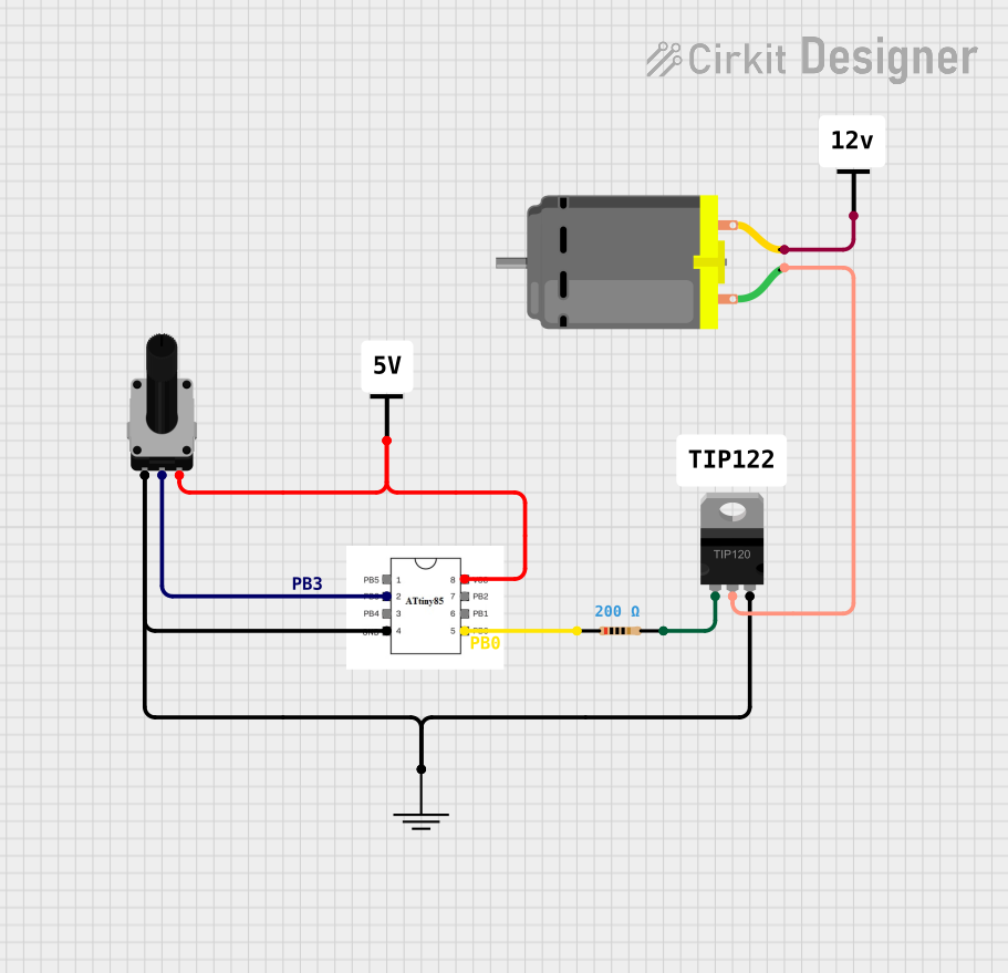
Circuit Documentation
Summary of the Circuit
This circuit appears to be designed to control a DC motor's speed using a rotary potentiometer. The control logic is managed by an ATtiny85 microcontroller, which likely reads the potentiometer's position and adjusts the motor speed accordingly. A TIP120 Darlington transistor is used to drive the motor, as it requires more current than the microcontroller can directly supply. The circuit also includes a resistor, which is probably used to limit the current to the transistor's base. Power is supplied to the circuit through two Vcc connections, and a common ground is used for the components.
Component List
Rotary Potentiometer
- Description: A variable resistor with three terminals: two fixed ends (legs) and one variable (wiper).
- Properties: 10,000 Ohms resistance.
DC Motor
- Description: An electric motor that runs on direct current (DC) electricity.
- Properties: Not specified.
Vcc
- Description: Power supply connections for the circuit.
- Properties: Not specified.
TIP120 Hi-Current Darlington Transistor
- Description: A transistor used for controlling high current loads.
- Properties: Not specified.
Resistor
- Description: A passive two-terminal electrical component that implements electrical resistance as a circuit element.
- Properties: 200 Ohms resistance.
GND
- Description: Ground connection for the circuit.
- Properties: Not specified.
ATtiny85
- Description: A small and versatile 8-bit microcontroller.
- Properties: Not specified.
Comments
- Description: Placeholder for additional notes or comments in the circuit.
- Properties: Not specified.
Wiring Details
Rotary Potentiometer
- leg1: Connected to GND.
- wiper: Connected to ATtiny85 pin PB3.
- leg2: Connected to Vcc.
DC Motor
- pin 1: Connected to the COLLECTOR of the TIP120 transistor.
- pin 2: Connected to Vcc.
Vcc
- Provides power to the ATtiny85, Rotary Potentiometer, and one terminal of the DC Motor.
TIP120 Hi-Current Darlington Transistor
- BASE: Connected to one end of the Resistor.
- COLLECTOR: Connected to pin 1 of the DC Motor.
- EMITTER: Connected to GND.
Resistor
- pin1: Connected to ATtiny85 pin PB0.
- pin2: Connected to the BASE of the TIP120 transistor.
GND
- Common ground for the ATtiny85, Rotary Potentiometer, and EMITTER of the TIP120 transistor.
ATtiny85
- PB0: Connected to one end of the Resistor.
- PB3: Connected to the wiper of the Rotary Potentiometer.
- GND: Connected to GND.
- VCC: Connected to Vcc.
Documented Code
No code was provided for the ATtiny85 microcontroller. The expected code would likely include routines for reading the analog value from the potentiometer and using that value to generate a PWM signal to control the TIP120 transistor, which in turn controls the speed of the DC motor.