
Circuit Documentation
Summary of the Circuit
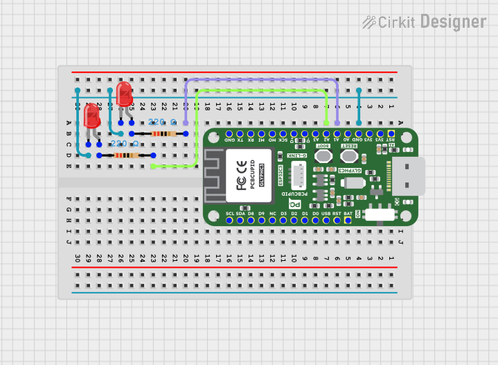
This circuit appears to be a simple LED driving circuit that uses a microcontroller to control two LEDs through current-limiting resistors. The microcontroller in use is a Glyph C3, which has a variety of GPIO pins. Each LED is connected to the microcontroller via a resistor, and the cathodes of both LEDs are connected to the ground. The anodes of the LEDs are connected to the microcontroller through the resistors, which are likely used to limit the current to the LEDs to prevent damage.
Component List
LED: Two Pin (red)
- Description: A standard red LED with two pins: anode and cathode.
- Purpose: To emit light when powered.
Resistor
- Description: A passive two-pin component that provides resistance to the flow of current.
- Properties: 220 Ohms resistance.
- Purpose: To limit the current flowing through the LEDs to prevent damage.
Glyph C3
- Description: A microcontroller with multiple GPIO pins and other functionalities.
- Purpose: To control the operation of the LEDs, potentially enabling them to be turned on or off programmatically.
Wiring Details
LED: Two Pin (red)
- Cathode: Connected to the ground (GND) of the Glyph C3 microcontroller.
- Anode: Connected to one of the pins of a resistor.
Resistor
- Pin1: Connected to the anode of an LED.
- Pin2: Connected to a GPIO pin on the Glyph C3 microcontroller (A1 / IO1 for one resistor and A3 / IO2 for the other).
Glyph C3
- GND: Connected to the cathodes of both LEDs.
- A1 / IO1: Connected to pin2 of one of the resistors.
- A3 / IO2: Connected to pin2 of the other resistor.
Documented Code
No code has been provided for the microcontroller. In a typical application, the microcontroller would be programmed to control the state of the GPIO pins connected to the LEDs, thus turning the LEDs on or off. The code would be responsible for setting up the GPIO pins as outputs and then toggling them according to the desired behavior (e.g., blinking, patterns, etc.).
Since no code is available, this section cannot be completed. However, if code were provided, it would be documented here with explanations of its functionality and how it interacts with the hardware components listed above.