
Arduino UNO-Based Line Following and Obstacle Avoidance Robot with Ultrasonic and IR Sensors
View and Edit Project In Cirkit Designer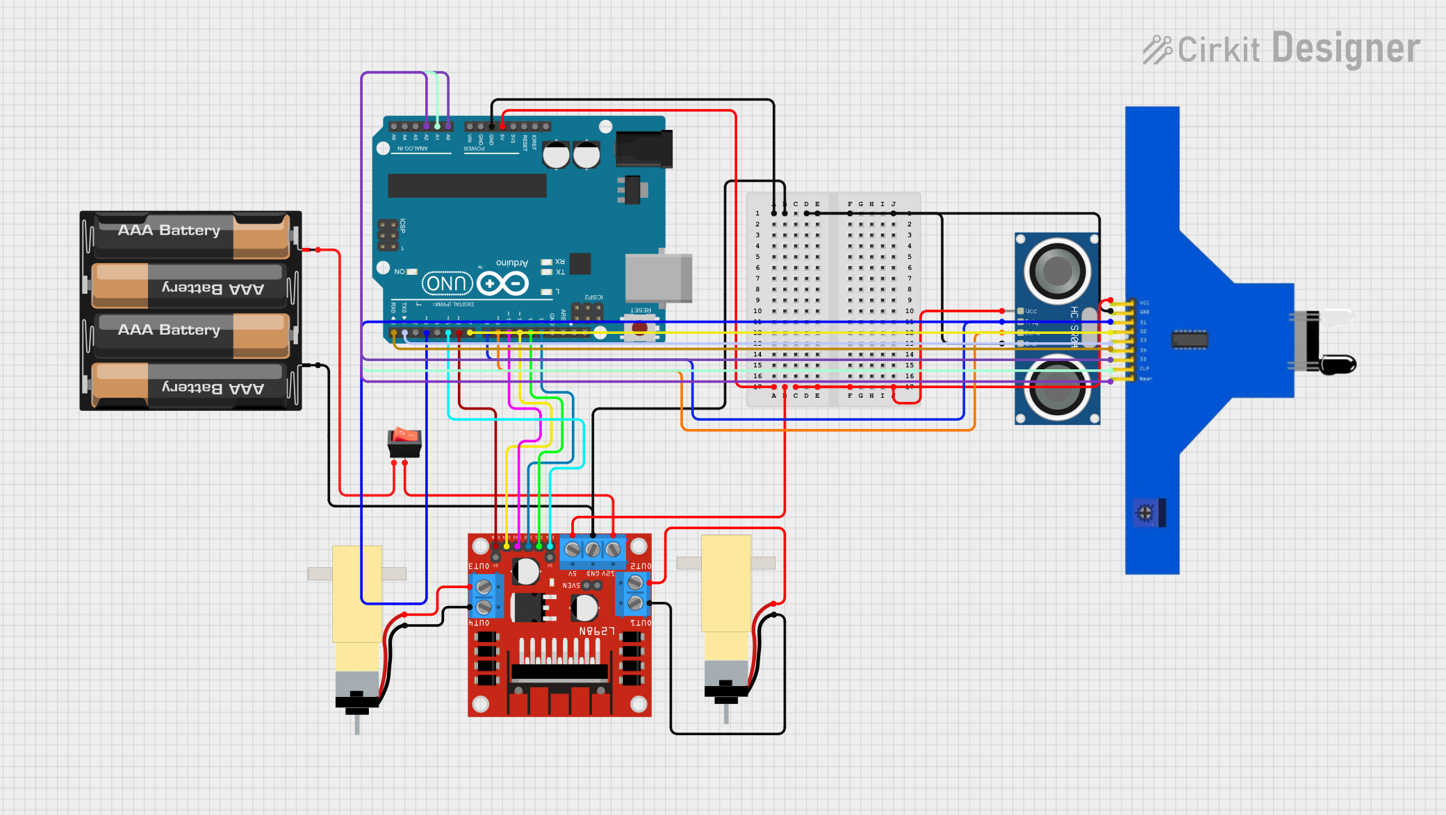
Circuit Documentation
Summary
This document provides a detailed overview of a circuit designed to control a robot using an Arduino UNO. The circuit includes various sensors and actuators, such as an ultrasonic sensor, IR sensors, and DC motors, all interfaced through an L298N motor driver. The robot is powered by a 4 x AAA battery mount and includes a rocker switch for power control.
Component List
4 x AAA Battery Mount
- Description: Battery holder for 4 AAA batteries.
- Pins:
-,+
HC-SR04 Ultrasonic Sensor
- Description: Ultrasonic distance sensor.
- Pins:
VCC,TRIG,ECHO,GND
L298N DC Motor Driver
- Description: Dual H-Bridge motor driver.
- Pins:
OUT1,OUT2,12V,GND,5V,OUT3,OUT4,5V-ENA-JMP-I,5V-ENA-JMP-O,+5V-J1,+5V-J2,ENA,IN1,IN2,IN3,IN4,ENB
Rocker Switch
- Description: On/Off switch.
- Pins:
output,input
Hobby Gearmotor with 48:1 Gearbox
- Description: DC motor with a 48:1 gearbox.
- Pins:
pin 1,pin 2
Arduino UNO
- Description: Microcontroller board based on the ATmega328P.
- Pins:
UNUSED,IOREF,Reset,3.3V,5V,GND,Vin,A0,A1,A2,A3,A4,A5,SCL,SDA,AREF,D13,D12,D11,D10,D9,D8,D7,D6,D5,D4,D3,D2,D1,D0
5 Channel IR Sensor
- Description: Infrared sensor array.
- Pins:
VCC,GND,S1,S2,S3,S4,S5,CLP,Near
Wiring Details
4 x AAA Battery Mount
-connected to:- HC-SR04 Ultrasonic Sensor
GND - Arduino UNO
GND - 5 Channel IR Sensor
GND - L298N DC Motor Driver
GND
- HC-SR04 Ultrasonic Sensor
+connected to:- Rocker Switch
input
- Rocker Switch
HC-SR04 Ultrasonic Sensor
GNDconnected to:- 4 x AAA Battery Mount
-
- 4 x AAA Battery Mount
VCCconnected to:- Arduino UNO
5V - 5 Channel IR Sensor
VCC - L298N DC Motor Driver
5V
- Arduino UNO
TRIGconnected to:- Arduino UNO
D8
- Arduino UNO
ECHOconnected to:- Arduino UNO
D9
- Arduino UNO
L298N DC Motor Driver
GNDconnected to:- 4 x AAA Battery Mount
-
- 4 x AAA Battery Mount
5Vconnected to:- HC-SR04 Ultrasonic Sensor
VCC - Arduino UNO
5V - 5 Channel IR Sensor
VCC
- HC-SR04 Ultrasonic Sensor
12Vconnected to:- Rocker Switch
output
- Rocker Switch
IN1connected to:- Arduino UNO
D12
- Arduino UNO
IN2connected to:- Arduino UNO
D13
- Arduino UNO
IN3connected to:- Arduino UNO
D10
- Arduino UNO
IN4connected to:- Arduino UNO
D11
- Arduino UNO
ENAconnected to:- Arduino UNO
D5
- Arduino UNO
ENBconnected to:- Arduino UNO
D6
- Arduino UNO
OUT1connected to:- Hobby Gearmotor with 48:1 Gearbox
pin 1
- Hobby Gearmotor with 48:1 Gearbox
OUT2connected to:- Hobby Gearmotor with 48:1 Gearbox
pin 2
- Hobby Gearmotor with 48:1 Gearbox
OUT3connected to:- Hobby Gearmotor with 48:1 Gearbox
pin 2
- Hobby Gearmotor with 48:1 Gearbox
OUT4connected to:- Hobby Gearmotor with 48:1 Gearbox
pin 1
- Hobby Gearmotor with 48:1 Gearbox
Rocker Switch
inputconnected to:- 4 x AAA Battery Mount
+
- 4 x AAA Battery Mount
outputconnected to:- L298N DC Motor Driver
12V
- L298N DC Motor Driver
Hobby Gearmotor with 48:1 Gearbox
pin 1connected to:- L298N DC Motor Driver
OUT1 - L298N DC Motor Driver
OUT4
- L298N DC Motor Driver
pin 2connected to:- L298N DC Motor Driver
OUT2 - L298N DC Motor Driver
OUT3
- L298N DC Motor Driver
Arduino UNO
GNDconnected to:- 4 x AAA Battery Mount
-
- 4 x AAA Battery Mount
5Vconnected to:- HC-SR04 Ultrasonic Sensor
VCC - 5 Channel IR Sensor
VCC - L298N DC Motor Driver
5V
- HC-SR04 Ultrasonic Sensor
D8connected to:- HC-SR04 Ultrasonic Sensor
TRIG
- HC-SR04 Ultrasonic Sensor
D9connected to:- HC-SR04 Ultrasonic Sensor
ECHO
- HC-SR04 Ultrasonic Sensor
D13connected to:- L298N DC Motor Driver
IN2
- L298N DC Motor Driver
D12connected to:- L298N DC Motor Driver
IN1
- L298N DC Motor Driver
D11connected to:- L298N DC Motor Driver
IN4
- L298N DC Motor Driver
D10connected to:- L298N DC Motor Driver
IN3
- L298N DC Motor Driver
D7connected to:- 5 Channel IR Sensor
S2
- 5 Channel IR Sensor
D6connected to:- L298N DC Motor Driver
ENB
- L298N DC Motor Driver
D5connected to:- L298N DC Motor Driver
ENA
- L298N DC Motor Driver
D3connected to:- 5 Channel IR Sensor
S1
- 5 Channel IR Sensor
D1connected to:- 5 Channel IR Sensor
S3
- 5 Channel IR Sensor
D0connected to:- 5 Channel IR Sensor
S4
- 5 Channel IR Sensor
A0connected to:- 5 Channel IR Sensor
S5
- 5 Channel IR Sensor
A1connected to:- 5 Channel IR Sensor
CLP
- 5 Channel IR Sensor
A2connected to:- 5 Channel IR Sensor
Near
- 5 Channel IR Sensor
5 Channel IR Sensor
GNDconnected to:- 4 x AAA Battery Mount
-
- 4 x AAA Battery Mount
VCCconnected to:- HC-SR04 Ultrasonic Sensor
VCC - Arduino UNO
5V - L298N DC Motor Driver
5V
- HC-SR04 Ultrasonic Sensor
S1connected to:- Arduino UNO
D3
- Arduino UNO
S2connected to:- Arduino UNO
D7
- Arduino UNO
S3connected to:- Arduino UNO
D1
- Arduino UNO
S4connected to:- Arduino UNO
D0
- Arduino UNO
S5connected to:- Arduino UNO
A0
- Arduino UNO
CLPconnected to:- Arduino UNO
A1
- Arduino UNO
Nearconnected to:- Arduino UNO
A2
- Arduino UNO
Documented Code
// Definición pines EnA y EnB para el control de la velocidad
int VelocidadMotor1 = 6;
int VelocidadMotor2 = 5;

// Definición de los pines de control de giro de los motores In1, In2, In3 e In4
int Motor1A = 13;
int Motor1B = 12;
int Motor2C = 11;
int Motor2D = 10;

// Sensores infrarrojo - izquierdo y derecho
int infraPin  = 2;
int infraPin1 = 4;

// Variables para la captura de los valores: 0 - fondo claro y 1 - línea negra
int valorInfra = 0;
int valorInfra1 = 0;

// Ultrasonicos
#define PIN_TRIG 9
#define PIN_ECHO 8

long duration, distancia;
// Configuración inicial
void setup() {
  Serial.begin(9600);

  delay(1000);
  //configuración del ultrasonico
  pinMode(PIN_TRIG, OUTPUT);
  pinMode(PIN_ECHO, INPUT);
  // Establecemos modo de los pines de los sensores infrarrojo
  pinMode(infraPin, INPUT);
  pinMode(infraPin1, INPUT);

  // Establecemos modo de los pines del control de motores
  pinMode(Motor1A,OUTPUT);
  pinMode(Motor1B,OUTPUT);
  pinMode(Motor2C,OUTPUT);
  pinMode(Motor2D,OUTPUT);
  pinMode(VelocidadMotor1, OUTPUT);
  pinMode(VelocidadMotor2, OUTPUT);

  // Configuramos los