
Circuit Documentation
Summary
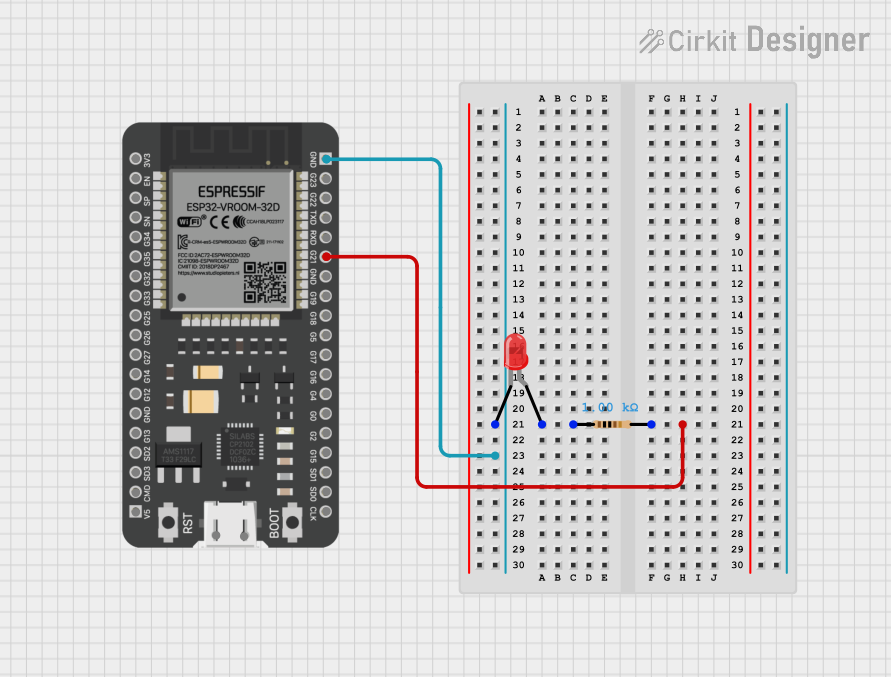
This document provides a detailed overview of a simple circuit consisting of an ESP32 microcontroller, a resistor, and a red LED. The circuit is designed to demonstrate basic connectivity and control using the ESP32.
Component List
Resistor
- Component Name: Resistor
- Description: A resistor with a resistance of 1000 Ohms.
- Pins: pin1, pin2
- Properties:
- Resistance: 1000 Ohms
LED: Two Pin (red)
- Component Name: LED: Two Pin (red)
- Description: A red LED with two pins: cathode and anode.
- Pins: cathode, anode
ESP32 - 38 pins
- Component Name: ESP32 - 38 pins
- Description: A microcontroller with 38 pins.
- Pins: 3V3, EN, SP, SN, G34, G35, G32, G33, G25, G26, G27, G14, G12, GND, G13, SD2, SD3, CMD, 5V, G23, G22, TXD, RXD, G21, G19, G18, G5, G17, G16, G4, G0, G2, G15, SD1, SD0, CLK
Wiring Details
Resistor
- Pin1: Connected to the anode of the LED.
- Pin2: Connected to pin G21 of the ESP32.
LED: Two Pin (red)
- Anode: Connected to pin1 of the resistor.
- Cathode: Connected to the GND pin of the ESP32.
ESP32 - 38 pins
- Pin G21: Connected to pin2 of the resistor.
- Pin GND: Connected to the cathode of the LED.
Code Documentation
ESP32 Code
void setup() {
  // put your setup code here, to run once:

}

void loop() {
  // put your main code here, to run repeatedly:

}
Additional Documentation
This document provides a comprehensive overview of the circuit, including the components used, their connections, and the code for the ESP32 microcontroller.