
Raspberry Pi 4B Controlled DC Motor with OLED Feedback Display
View and Edit Project In Cirkit Designer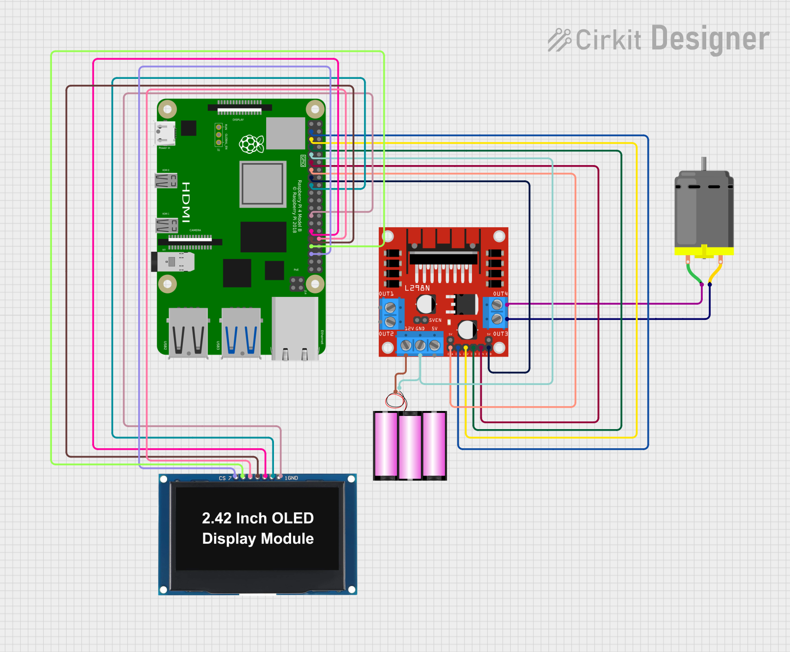
Circuit Documentation
Summary
This circuit is designed to control a DC motor using an L298N motor driver module, with a Raspberry Pi 4B as the main controller. The circuit also includes an OLED display to provide visual feedback on the motor's status. The motor's direction and speed are controlled by the Raspberry Pi 4B through GPIO pins connected to the L298N driver. The OLED display is interfaced with the Raspberry Pi 4B to show the current status of the motor, such as "FORWARD", "BACKWARD", and "STOPPED".
Component List
Raspberry Pi 4B
- Microcontroller board with multiple GPIO pins for interfacing with peripherals.
- Provides the processing power for controlling the motor driver and the OLED display.
L298N DC Motor Driver
- An H-bridge motor driver that allows for controlling the direction and speed of a DC motor.
- It receives control signals from the Raspberry Pi 4B and drives the motor accordingly.
DC Motor
- A simple electric motor that converts electrical energy into mechanical motion.
- It is driven by the L298N motor driver in this circuit.
OLED Display 2.42"
- A small display that provides visual feedback on the system status.
- It is controlled by the Raspberry Pi 4B via I2C communication.
Battery 12V
- A power source for the motor driver and the DC motor.
- It provides the necessary voltage and current to drive the motor.
Wiring Details
Raspberry Pi 4B
GPIO2connected to L298NIN1GPIO3connected to L298NIN2GPIO4connected to L298NIN3GPIO17connected to L298NIN4GPIO27connected to L298NENAGPIO22connected to L298NENB3V3connected to OLED DisplayVCCGNDconnected to OLED DisplayGND, L298NGND, and Battery-GPIO5connected to OLED DisplaySCKGPIO6connected to OLED DisplaySDAGPIO12connected to OLED DisplayRESGPIO13connected to OLED DisplayDCGPIO19connected to OLED DisplayCS
L298N DC Motor Driver
OUT1andOUT2(not used in this circuit)12Vconnected to Battery+GNDconnected to Raspberry Pi 4BGNDand Battery-5V,5V-ENA-JMP-I,5V-ENA-JMP-O,+5V-J1,+5V-J2(not used in this circuit)OUT3connected to DC Motorpin 2OUT4connected to DC Motorpin 1ENAconnected to Raspberry Pi 4BGPIO27IN1connected to Raspberry Pi 4BGPIO2IN2connected to Raspberry Pi 4BGPIO3IN3connected to Raspberry Pi 4BGPIO4IN4connected to Raspberry Pi 4BGPIO17ENBconnected to Raspberry Pi 4BGPIO22
DC Motor
pin 1connected to L298NOUT4pin 2connected to L298NOUT3
OLED Display 2.42"
GNDconnected to Raspberry Pi 4BGNDVCCconnected to Raspberry Pi 4B3V3SCKconnected to Raspberry Pi 4BGPIO5SDAconnected to Raspberry Pi 4BGPIO6RESconnected to Raspberry Pi 4BGPIO12DCconnected to Raspberry Pi 4BGPIO13CSconnected to Raspberry Pi 4BGPIO19
Battery 12V
+connected to L298N12V-connected to Raspberry Pi 4BGNDand L298NGND
Documented Code
/*
 * This Arduino Sketch controls a DC motor using an L298N motor driver and
 * displays status on an OLED display. The Raspberry Pi 4B is used to
 * interface with the motor driver and the OLED display. The motor is
 * controlled via GPIO pins connected to the L298N driver, and the OLED
 * display shows the motor status.
 */

#include <Wire.h>
#include <Adafruit_GFX.h>
#include <Adafruit_SSD1306.h>

#define SCREEN_WIDTH 128
#define SCREEN_HEIGHT 64
#define OLED_RESET -1
Adafruit_SSD1306 display(SCREEN_WIDTH, SCREEN_HEIGHT, &Wire, OLED_RESET);

// Motor driver pins
const int IN1 = 2;
const int IN2 = 3;
const int IN3 = 4;
const int IN4 = 17;
const int ENA = 27;
const int ENB = 22;

void setup() {
  // Initialize motor driver pins
  pinMode(IN1, OUTPUT);
  pinMode(IN2, OUTPUT);
  pinMode(IN3, OUTPUT);
  pinMode(IN4, OUTPUT);
  pinMode(ENA, OUTPUT);
  pinMode(ENB, OUTPUT);

  // Initialize OLED display
  if(!display.begin(SSD1306_SWITCHCAPVCC, 0x3C)) {
    Serial.println(F("SSD1306 allocation failed"));
    for(;;);
  }
  display.display();
  delay(2000);
  display.clearDisplay();

  // Display initial message
  display.setTextSize(1);
  display.setTextColor(SSD1306_WHITE);
  display.setCursor(0, 0);
  display.println(F("Motor Control Initialized"));
  display.display();
}

void loop() {
  // Motor forward
  digitalWrite(IN1, HIGH);
  digitalWrite(IN2, LOW);
  digitalWrite(IN3, HIGH);
  digitalWrite(IN4, LOW);
  analogWrite(ENA, 255);
  analogWrite(ENB, 255);

  // Update display
  display.clearDisplay();
  display.setCursor(0, 0);
  display.println(F("Motor Status: FORWARD"));
  display.display();
  delay(2000);

  // Motor backward
  digitalWrite(IN1, LOW);
  digitalWrite(IN2, HIGH);
  digitalWrite(IN3, LOW);
  digitalWrite(IN4, HIGH);
  analogWrite(ENA, 255);
  analogWrite(ENB, 255);

  // Update display
  display.clearDisplay();
  display.setCursor(0, 0);
  display.println(F("Motor Status: BACKWARD"));
  display.display();
  delay(2000);

  // Motor stop
  digitalWrite(IN1, LOW);
  digitalWrite(IN2, LOW);
  digitalWrite(IN3, LOW);
  digitalWrite(IN4, LOW);
  analogWrite(ENA, 0);
  analogWrite(ENB, 0);

  // Update display
  display.clearDisplay();
  display.setCursor(0, 0);
  display.println(F("Motor Status: STOPPED"));
  display.display();
  delay(2000);
}
This code is designed to run on a Raspberry Pi 4B, which is not typically programmed using Arduino sketches. However, the code provided is written in the style of an Arduino sketch, which suggests that it may be intended for use with an Arduino-compatible environment on the Raspberry Pi, such as using the Arduino IDE with an add-on for Raspberry Pi GPIO programming.