
Arduino Nano-Based Smart Home Automation System with IR Sensor and LCD Display
View and Edit Project In Cirkit Designer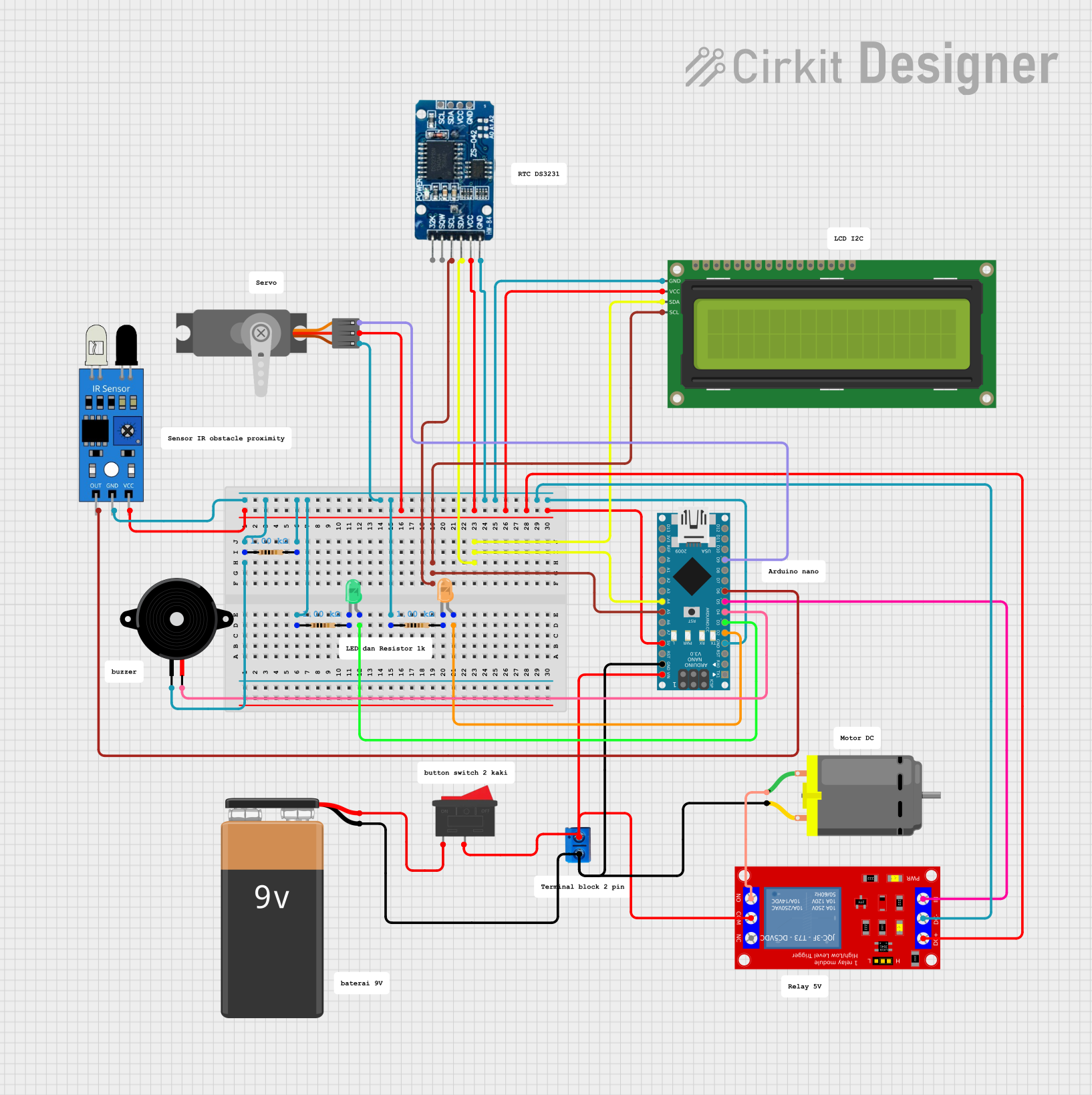
Circuit Documentation
Summary
This circuit involves various components including a Rocker Switch, a 9V Battery, an IR Sensor, a 16x2 I2C LCD, a 1 Channel 5V Relay Module, a DC Motor, two LEDs (green and orange), several Resistors, a Terminal PCB 2 Pin, an Arduino Nano, a Servo, an RTC DS3231, and a Piezo Speaker. The circuit is designed to interface these components with an Arduino Nano microcontroller, which controls the operation of the LEDs, motor, relay, and other peripherals based on inputs from sensors and other components.
Component List
Rocker Switch
- Description: A simple on/off switch.
- Pins: 1, 2
9V Battery
- Description: Provides power to the circuit.
- Pins: +, -
IR Sensor
- Description: Detects infrared light.
- Pins: out, gnd, vcc
16x2 I2C LCD
- Description: A 16x2 character LCD with I2C interface.
- Pins: GND, VCC, SDA, SCL
1 Channel 5V Relay Module
- Description: A relay module for switching high power devices.
- Pins: VCC+, VCC- (GND), IN, N.O., COM, N.C.
DC Motor
- Description: A simple DC motor.
- Pins: pin 1, pin 2
LED: Two Pin (green)
- Description: A green LED.
- Pins: cathode, anode
LED: Two Pin (orange)
- Description: An orange LED.
- Pins: cathode, anode
Resistor
- Description: A resistor with 1000 Ohms resistance.
- Pins: pin1, pin2
Terminal PCB 2 Pin
- Description: A terminal block for connecting wires.
- Pins: Pin A, Pin B
Arduino Nano
- Description: A small, complete, and breadboard-friendly board based on the ATmega328.
- Pins: D1/TX, D0/RX, RESET, GND, D2, D3, D4, D5, D6, D7, D8, D9, D10, D11/MOSI, D12/MISO, VIN, 5V, A7, A6, A5, A4, A3, A2, A1, A0, AREF, 3V3, D13/SCK
Servo (Wokwi Compatible)
- Description: A servo motor compatible with Wokwi.
- Pins: GND, V+, PWM
RTC DS3231
- Description: A real-time clock module.
- Pins: 32K, SQW, SCL, SDA, VCC, GND
Piezo Speaker
- Description: A piezoelectric speaker.
- Pins: pin1, pin2
Wiring Details
Rocker Switch
- Pin 1: Connected to the positive terminal of the 9V Battery.
- Pin 2: Connected to the COM pin of the 1 Channel 5V Relay Module and Pin B of the Terminal PCB 2 Pin.
9V Battery
- + Pin: Connected to Pin 1 of the Rocker Switch.
- - Pin: Connected to Pin 2 of the DC Motor and GND of the Arduino Nano.
IR Sensor
- out Pin: Connected to D6 of the Arduino Nano.
- gnd Pin: Connected to GND (common ground).
- vcc Pin: Connected to V+ of the Servo, VCC of the RTC DS3231, VCC of the 16x2 I2C LCD, VCC+ of the 1 Channel 5V Relay Module, and 5V of the Arduino Nano.
16x2 I2C LCD
- GND Pin: Connected to GND (common ground).
- VCC Pin: Connected to VCC (common power).
- SDA Pin: Connected to A4 of the Arduino Nano and SDA of the RTC DS3231.
- SCL Pin: Connected to A5 of the Arduino Nano and SCL of the RTC DS3231.
1 Channel 5V Relay Module
- VCC+ Pin: Connected to VCC (common power).
- VCC- (GND) Pin: Connected to GND (common ground).
- IN Pin: Connected to D5 of the Arduino Nano.
- N.O. Pin: Connected to pin 1 of the DC Motor.
- COM Pin: Connected to Pin 2 of the Rocker Switch and Pin B of the Terminal PCB 2 Pin.
DC Motor
- pin 1: Connected to N.O. of the 1 Channel 5V Relay Module.
- pin 2: Connected to Pin A of the Terminal PCB 2 Pin and GND of the Arduino Nano.
LED: Two Pin (green)
- anode Pin: Connected to D3 of the Arduino Nano.
- cathode Pin: Connected to pin2 of the Resistor.
LED: Two Pin (orange)
- anode Pin: Connected to D2 of the Arduino Nano.
- cathode Pin: Connected to pin2 of the Resistor.
Resistor
- pin1: Connected to pin1 of the Piezo Speaker, pin1 of another Resistor, pin2 of another Resistor, pin1 of another Resistor, and GND of the IR Sensor.
- pin2: Connected to cathode of the green LED and cathode of the orange LED.
Terminal PCB 2 Pin
- Pin A: Connected to pin 2 of the DC Motor and GND of the Arduino Nano.
- Pin B: Connected to COM of the 1 Channel 5V Relay Module and Pin 2 of the Rocker Switch.
Arduino Nano
- GND Pin: Connected to GND (common ground).
- D2 Pin: Connected to anode of the orange LED.
- D3 Pin: Connected to anode of the green LED.
- D4 Pin: Connected to pin2 of the Piezo Speaker.
- D5 Pin: Connected to IN of the 1 Channel 5V Relay Module.
- D6 Pin: Connected to out of the IR Sensor.
- D9 Pin: Connected to PWM of the Servo.
- A4 Pin: Connected to SDA of the 16x2 I2C LCD and SDA of the RTC DS3231.
- A5 Pin: Connected to SCL of the 16x2 I2C LCD and SCL of the RTC DS3231.
- 5V Pin: Connected to VCC (common power).
- VIN Pin: Connected to Pin B of the Terminal PCB 2 Pin.
Servo (Wokwi Compatible)
- GND Pin: Connected to GND (common ground).
- V+ Pin: Connected to VCC (common power).
- PWM Pin: Connected to D9 of the Arduino Nano.
RTC DS3231
- GND Pin: Connected to GND (common ground).
- VCC Pin: Connected to VCC (common power).
- SDA Pin: Connected to A4 of the Arduino Nano and SDA of the 16x2 I2C LCD.
- SCL Pin: Connected to A5 of the Arduino Nano and SCL of the 16x2 I2C LCD.
Piezo Speaker
- pin1: Connected to pin1 of the Resistor.
- pin2: Connected to D4 of the Arduino Nano.
Documented Code
Arduino Nano Code
void setup() {
  // put your setup code here, to run once:

}

void loop() {
  // put your main code here, to run repeatedly:

}
This code is a basic template for the Arduino Nano. The setup() function is where you initialize your components and settings, and the loop() function is where you place the main code that runs repeatedly.