
Arduino Mega 2560 Controlled Relay and Stepper Driver System with I2C DAC and RC Receiver
View and Edit Project In Cirkit Designer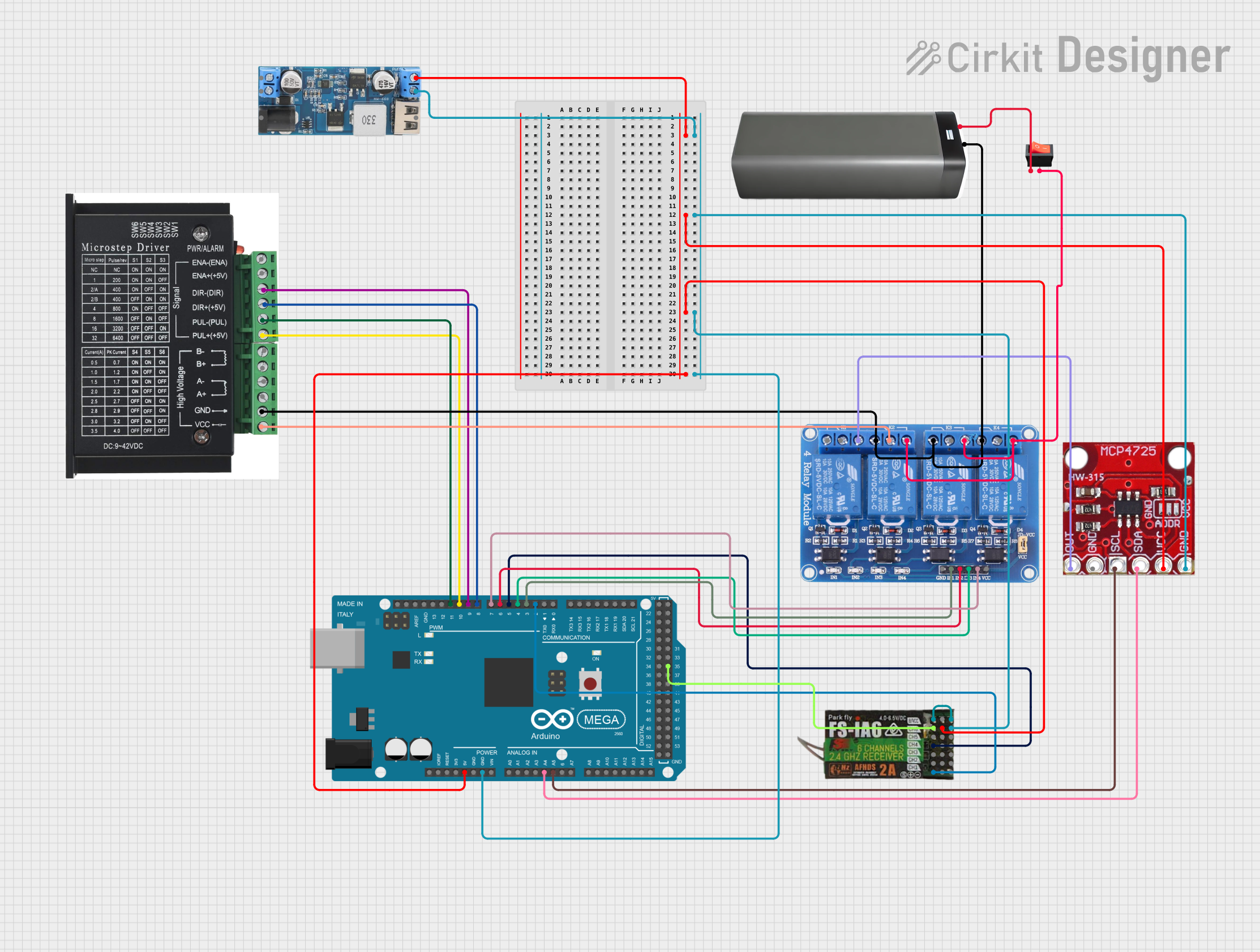
Circuit Documentation
Summary
This circuit integrates various components to perform a set of functions controlled by an Arduino Mega 2560 microcontroller. The circuit includes a DAC module for analog output, a stepper driver for motor control, a 4-channel relay module for switching high-power devices, a receiver module for remote control, a power converter to step down voltage from 12V to 5V, a battery pack as a power source, and a rocker switch as a user interface element.
Component List
Arduino Mega 2560
- Microcontroller board based on the ATmega2560
- It has 54 digital input/output pins (of which 15 can be used as PWM outputs), 16 analog inputs, 4 UARTs (hardware serial ports), a 16 MHz crystal oscillator, a USB connection, a power jack, an ICSP header, and a reset button.
xcluma MCP4725 I2C DAC Breakout Module
- Digital-to-Analog Converter (DAC) module with I2C interface
- Provides analog output based on digital input received from the microcontroller.
Stepper Driver
- A driver module for controlling a stepper motor
- It has inputs for enabling the motor, setting the direction, and controlling the stepping pulses.
Relay 4 Channel 5V
- A 4-channel relay module for controlling up to four high-power devices
- Each channel has a Normally Open (NO) and a Normally Closed (NC) contact.
FLYSKY FS-IA6
- A 6-channel receiver for remote control applications
- It receives signals from a compatible transmitter and outputs control signals to the microcontroller.
12V to 5V Step Down Power Converter
- A DC-DC converter module that steps down the voltage from 12V to 5V
- It provides a regulated 5V output for powering the microcontroller and other 5V components.
Battery Pack
- A power source for the circuit
- Typically provides a voltage output suitable for the circuit's requirements.
Rocker Switch
- A switch to control the power flow in the circuit
- It allows the user to manually turn the circuit on or off.
Wiring Details
Arduino Mega 2560
5Vconnected to the 5V output from the step-down converter, DAC VCC, and receiver 5V.GNDconnected to the ground of the step-down converter, DAC GND, receiver GND, stepper driver GND, and relay GND.A4 (SDA)connected to DAC SDA.A5 (SCL)connected to DAC SCL.D2 PWMconnected to receiver CH1.D3 PWMconnected to relay IN1.D4 PWMconnected to relay IN3.D5 PWMconnected to receiver CH4.D6 PWMconnected to relay IN2.D7 PWMconnected to relay IN4.D8 PWMconnected to stepper driver DIR+.D9 PWMconnected to stepper driver DIR-.D10 PWMconnected to stepper driver PUL+.D11 PWMconnected to stepper driver PUL-.D35connected to receiver CH6.
xcluma MCP4725 I2C DAC Breakout Module
VCCconnected to 5V output from the step-down converter.GNDconnected to the common ground.SDAconnected to Arduino Mega 2560 A4.SCLconnected to Arduino Mega 2560 A5.OUTconnected to relay NO1.
Stepper Driver
DIR+connected to Arduino Mega 2560 D8 PWM.DIR-connected to Arduino Mega 2560 D9 PWM.PUL+connected to Arduino Mega 2560 D10 PWM.PUL-connected to Arduino Mega 2560 D11 PWM.GNDconnected to the common ground.VCCconnected to relay COM2.
Relay 4 Channel 5V
IN1connected to Arduino Mega 2560 D3 PWM.IN2connected to Arduino Mega 2560 D6 PWM.IN3connected to Arduino Mega 2560 D4 PWM.IN4connected to Arduino Mega 2560 D7 PWM.NO1connected to DAC OUT.NC2,NC3,NC4connected to the common ground.COM2connected to stepper driver VCC.NO2,NO3,NO4connected to the rocker switch output.
FLYSKY FS-IA6
5VandVCCconnected to 5V output from the step-down converter.GNDconnected to the common ground.CH1connected to Arduino Mega 2560 D2 PWM.CH4connected to Arduino Mega 2560 D5 PWM.CH6connected to Arduino Mega 2560 D35.
12V to 5V Step Down Power Converter
5v OUTPUTconnected to Arduino Mega 2560 5V, DAC VCC, and receiver 5V.GNDconnected to the common ground.
Battery Pack
+connected to the rocker switch input.-connected to the common ground, stepper driver GND, and relay NC2, NC3, NC4.
Rocker Switch
inputconnected to the battery pack +.outputconnected to relay NO2, NO3, NO4.
Documented Code
Arduino Mega 2560 Code (sketch.ino)
void setup() {
  // put your setup code here, to run once:

}

void loop() {
  // put your main code here, to run repeatedly:

}
Note: The provided code is a template and does not contain any functional code. It needs to be populated with the logic to control the components based on the requirements of the circuit.