
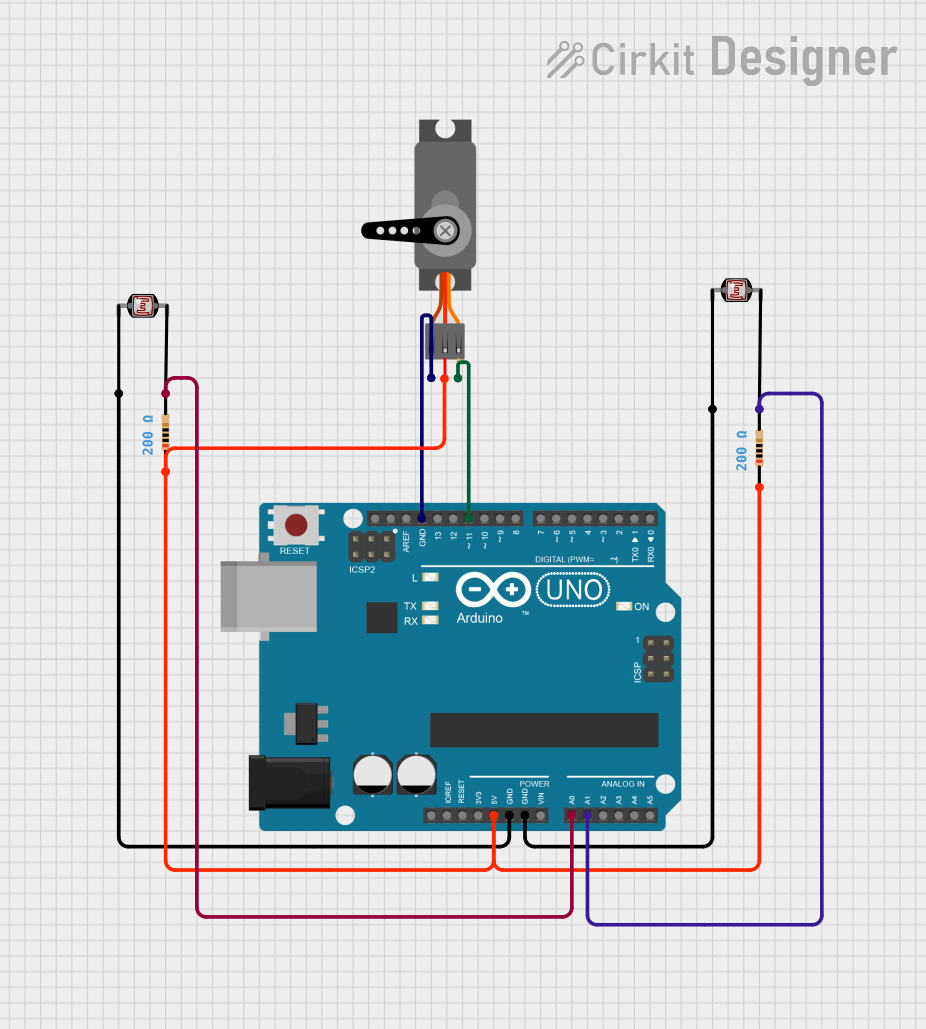
Circuit Documentation
Summary of the Circuit
This circuit is designed around an Arduino UNO microcontroller, which serves as the central processing unit. The circuit includes two photocells (Light Dependent Resistors or LDRs) for light sensing, two resistors that likely function as part of voltage dividers for the LDRs, and a servo motor that can be controlled by the Arduino. The Arduino is responsible for reading the analog values from the LDRs and controlling the position of the servo motor based on the program loaded into it.
Component List
Arduino UNO
- Description: A microcontroller board based on the ATmega328P.
- Purpose: Acts as the central processing unit of the circuit, reading sensor inputs and controlling outputs.
- Pins: UNUSED, IOREF, Reset, 3.3V, 5V, GND, Vin, A0-A5, SCL, SDA, AREF, D0-D13.
Photocell (LDR)
- Description: A light-sensitive device whose resistance changes with light intensity.
- Purpose: Used to sense the level of ambient light in the circuit.
Servo
- Description: An actuator that can be precisely controlled for position.
- Purpose: Receives signals from the Arduino to move to a specific orientation.
Resistor (200 Ohms)
- Description: A passive two-terminal electrical component that implements electrical resistance.
- Purpose: Likely used in conjunction with the LDRs to form a voltage divider for analog input to the Arduino.
Wiring Details
Arduino UNO
- 5V: Connected to the VCC of the Servo and one side of each 200 Ohm Resistor.
- GND: Connected to the GND of the Servo and one side of each Photocell (LDR).
- A0: Connected to the other side of one 200 Ohm Resistor.
- A1: Connected to the other side of the other 200 Ohm Resistor.
- D11: Connected to the PWM input of the Servo.
Photocell (LDR)
- pin 0: Connected to GND on the Arduino UNO.
- pin 1: Not connected in the provided net list.
Servo
- GND: Connected to GND on the Arduino UNO.
- VCC: Connected to 5V on the Arduino UNO.
- PWM: Connected to D11 on the Arduino UNO.
Resistor (200 Ohms)
- pin1: Connected to 5V on the Arduino UNO.
- pin2: Connected to A0 or A1 on the Arduino UNO (one resistor to A0, the other to A1).
Documented Code
Arduino UNO Code (sketch.ino)
void setup() {
  // put your setup code here, to run once:

}

void loop() {
  // put your main code here, to run repeatedly:

}
Note: The provided code is a template and does not contain any functional instructions. The user is expected to fill in the setup and loop functions with code that initializes the hardware components and contains the main logic for the circuit's operation.