Cirkit Designer
Your all-in-one circuit design IDE
Home /
Project Documentation
ESP32 Wi-Fi Controlled 220V Fan with Relay Module
Circuit Documentation
Summary
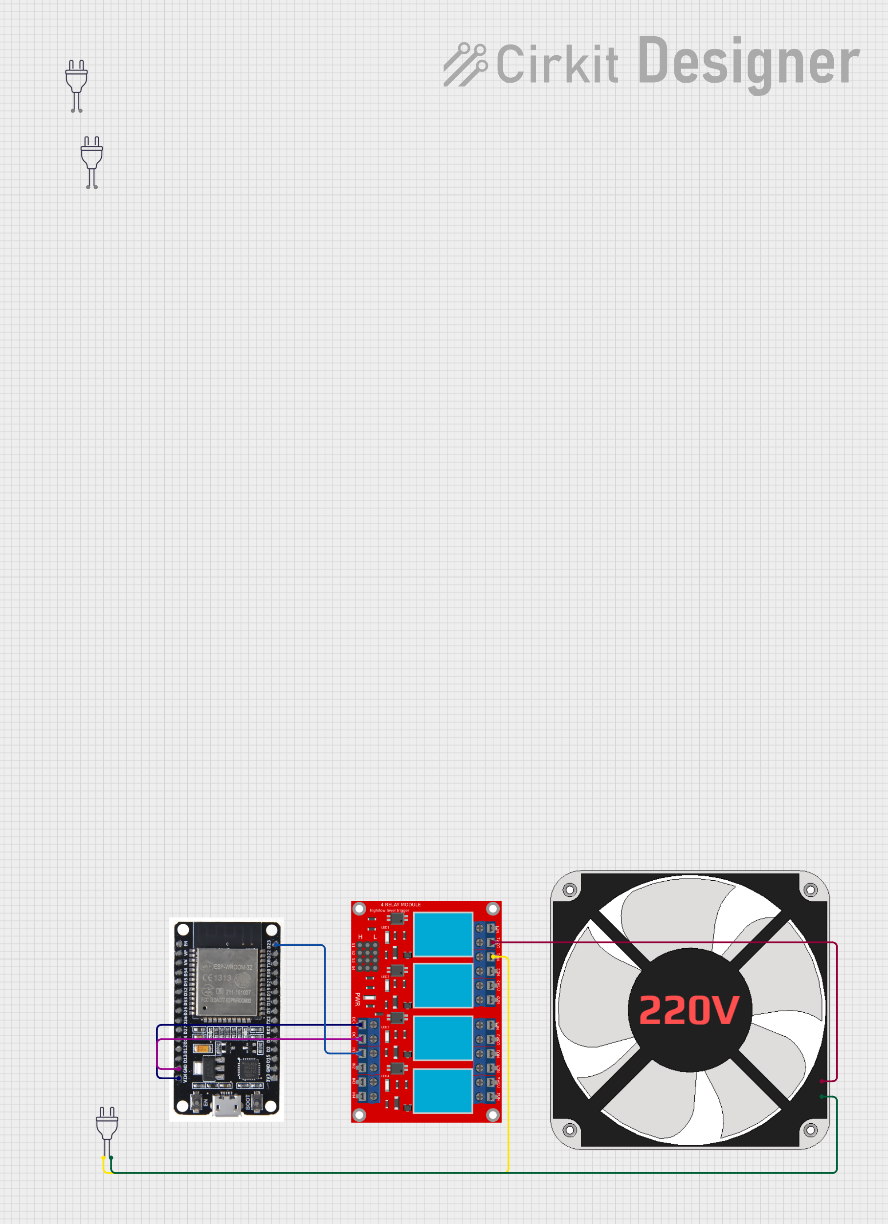
This document provides a detailed overview of a circuit that includes an ESP32 microcontroller, a 4-channel relay module, a 220V fan, and multiple 220V power sources. The ESP32 controls the relay module, which in turn controls the fan. The circuit is designed to activate the fan through the relay module when the ESP32 sets a specific pin high.
Component List
Power 220V
- Description: Provides 220V AC power.
- Pins: Hot wire, Neutral wire
ESP32
- Description: A microcontroller used to control the relay module.
- Pins: EN, VP, VN, D34, D35, D32, D33, D25, D26, D27, D14, D12, D13, GND, VIN, 3V3, D15, D2, D4, RX2, TX2, D5, D18, D19, D21, RX0, TX0, D22, D23, BOOT
4-Channel Relay Module
- Description: A relay module with 4 channels used to control high voltage devices.
- Pins: N.O. 4, COM 4, N.C. 4, N.O. 3, COM 3, N.C. 3, N.O. 2, COM 2, N.C. 2, N.O. 1, COM 1, N.C. 1, Pin 13, Pin 14, Pin 15, Pin 16, Pin 17, Pin 18, Pin 19, Pin 20, Pin 21, Pin 22, Pin 23, Pin 24, VCC+, VCC- (GND), IN 1, IN 2, IN 3, IN 4
220V Fan
- Description: A fan that operates on 220V AC.
- Pins: N, L
Wiring Details
Power 220V
Instance 1:
- Hot wire: Connected to N.O. 1 of the 4-channel relay module.
- Neutral wire: Connected to N of the 220V fan.
Instance 2:
- Hot wire: Not connected.
- Neutral wire: Not connected.
Instance 3:
- Hot wire: Connected to N.O. 1 of the 4-channel relay module.
- Neutral wire: Connected to N of the 220V fan.
ESP32
- GND: Connected to VCC- (GND) of the 4-channel relay module.
- VIN: Connected to VCC+ of the 4-channel relay module.
- D23: Connected to IN 1 of the 4-channel relay module.
4-Channel Relay Module
- N.O. 1: Connected to the hot wire of the 220V power source.
- COM 1: Connected to L of the 220V fan.
- VCC- (GND): Connected to GND of the ESP32.
- VCC+: Connected to VIN of the ESP32.
- IN 1: Connected to D23 of the ESP32.
220V Fan
- N: Connected to the neutral wire of the 220V power source.
- L: Connected to COM 1 of the 4-channel relay module.
Code Documentation
Code for ESP32
/*
 * This Arduino Sketch is for an ESP32 microcontroller in a circuit that includes
 * a 4-channel relay module and a 220V fan. The ESP32 controls the relay module
 * through its D23 pin. This code sets the D23 pin high to activate the relay.
 */

int relayPin = 23; // D23 pin connected to IN 1 of the relay module

void setup() {
  pinMode(relayPin, OUTPUT); // Set D23 as an output pin
  digitalWrite(relayPin, HIGH); // Set D23 pin high to activate the relay
}

void loop() {
  // Main code loop, currently empty as no repeated actions are required
}
This code initializes the D23 pin of the ESP32 as an output and sets it high to activate the relay connected to IN 1 of the 4-channel relay module. The relay, in turn, controls the 220V fan.