ESP8266 NodeMCU Controlled RFID Access System with LCD Feedback and Wi-Fi Connectivity
Circuit Documentation
Summary
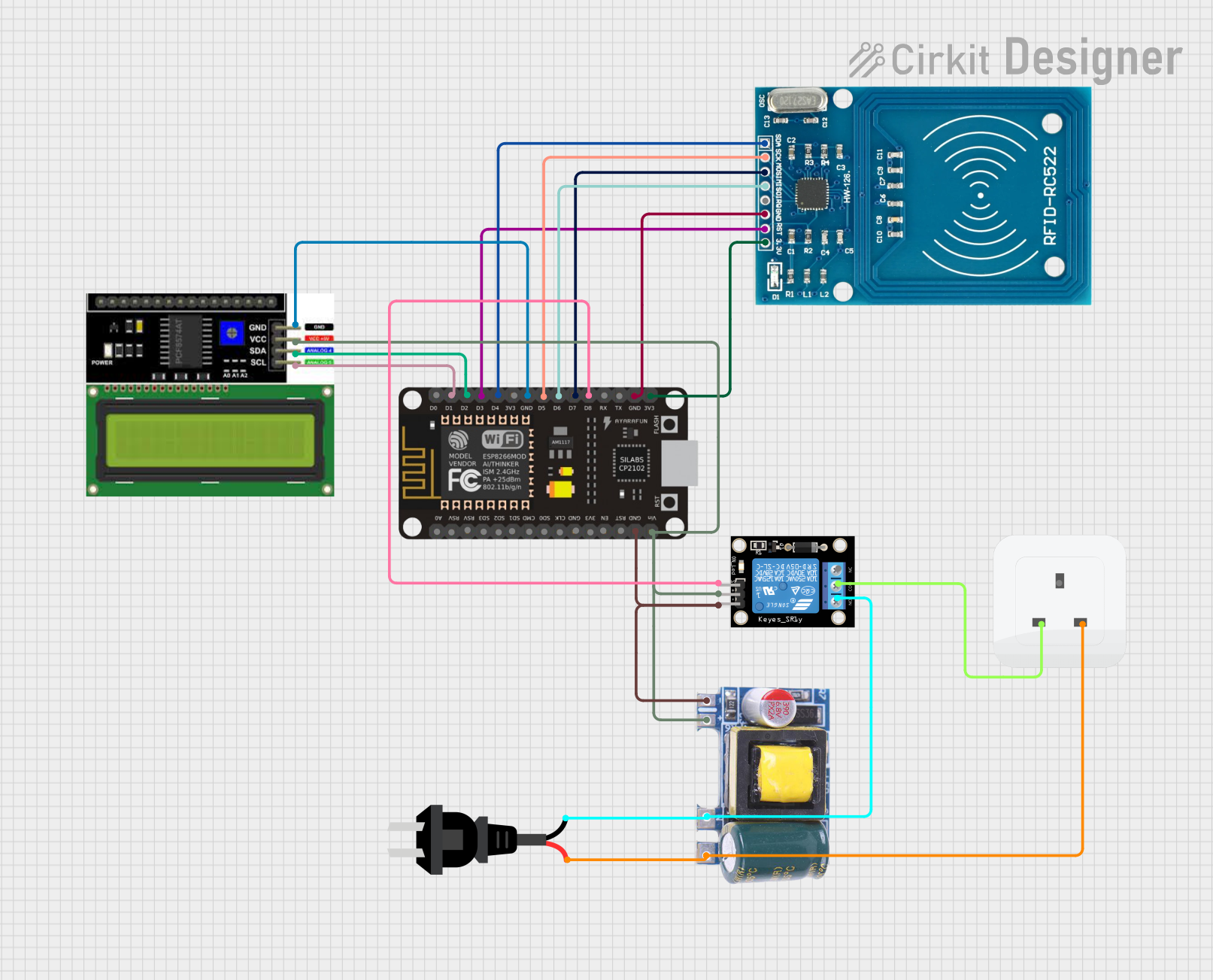
The circuit in question is designed to integrate an ESP8266 NodeMCU microcontroller with an LCD I2C display, an RFID-RC522 module, a single-channel relay module, and a power supply module. The ESP8266 NodeMCU serves as the central processing unit, handling Wi-Fi connectivity, RFID card reading, and user interface display on the LCD. The RFID-RC522 is used for scanning RFID tags, while the relay module controls an AC power source to a socket. The Mini AC-DC converter module steps down AC voltage to 5V required by the microcontroller and other components. The AC source provides the primary power to the system.
Component List
ESP8266 NodeMCU
- Description: A Wi-Fi enabled microcontroller module based on the ESP8266 chip.
- Pins: D0, D1, D2, D3, D4, 3V3, GND, D5, D6, D7, D8, RX, TX, A0, RSV, SD3, SD2, SD1, CMD, SD0, CLK, EN, RST, VIN
LCD I2C Display
- Description: A liquid crystal display that uses the I2C protocol for communication.
- Pins: GND, VCC, SDA, SCL
RFID-RC522
- Description: An RFID reader/writer module.
- Pins: VCC (3.3V), RST, GND, IRQ, MISO, MOSI, SCK, SDA
Relay Module 1 Channel
- Description: A module that allows for the control of high power devices using a low power signal.
- Pins: S, 5V, GND, NC, COM, NO
Socket
- Description: An interface for connecting an electrical device to the power supply.
- Pins: Earth, Life, Neutral
Mini AC-DC 110V-230V to 5V 700mA Module
- Description: A power supply module that converts AC voltage to 5V DC.
- Pins: GND, 5v, Neutral, Life
AC Source
- Description: The primary power source for the circuit.
- Pins: -, +
Wiring Details
ESP8266 NodeMCU
- D1 -> LCD I2C Display SCL
- D2 -> LCD I2C Display SDA
- D3 -> RFID-RC522 RST
- D4 -> RFID-RC522 SDA
- D5 -> RFID-RC522 SCK
- D6 -> RFID-RC522 MISO
- D7 -> RFID-RC522 MOSI
- D8 -> Relay Module S
- GND -> LCD I2C Display GND, RFID-RC522 GND, Relay Module GND, Mini AC-DC Module GND
- 3V3 -> RFID-RC522 VCC (3.3V)
- VIN -> Relay Module 5V, Mini AC-DC Module 5v, LCD I2C Display VCC
Relay Module 1 Channel
- COM -> Socket Life
- NO -> AC Source -
Mini AC-DC 110V-230V to 5V 700mA Module
- Neutral -> AC Source +
- Life -> Socket Neutral
Documented Code
Main Sketch (sketch.ino)
#include <SPI.h>
#include <MFRC522.h>
#include <Wire.h>
#include <LiquidCrystal_I2C.h>
#include <ESP8266WiFi.h>
#include "User.h"
#include "LibHelper.h"

// ... (code truncated for brevity)

void setup() {
  // Initialization code
}

void loop() {
  // Main loop code
}

// ... (additional functions and logic truncated for brevity)
LibHelper Header (LibHelper.h)
// LibHelper.h
#ifndef LIBHELPER_H
#define LIBHELPER_H

#include <Arduino.h>
#include <ArduinoJson.h>

class LibHelper {
public:
    static String postRequest(String link, String body);
};

#endif
LibHelper Implementation (LibHelper.txt)
The implementation for LibHelper is not provided in the input code. It is expected to contain the definitions for the declared functions in the header file.
This documentation provides an overview of the circuit, including a description of each component, wiring details, and the embedded code. The code is truncated for brevity, and it is assumed that the full implementation is available in the provided files.