Cirkit Designer
Your all-in-one circuit design IDE
Home /
Project Documentation
WiFi LoRa Environmental Monitoring System with INMP441 Mic and Multiple Sensors

Circuit Documentation
Summary
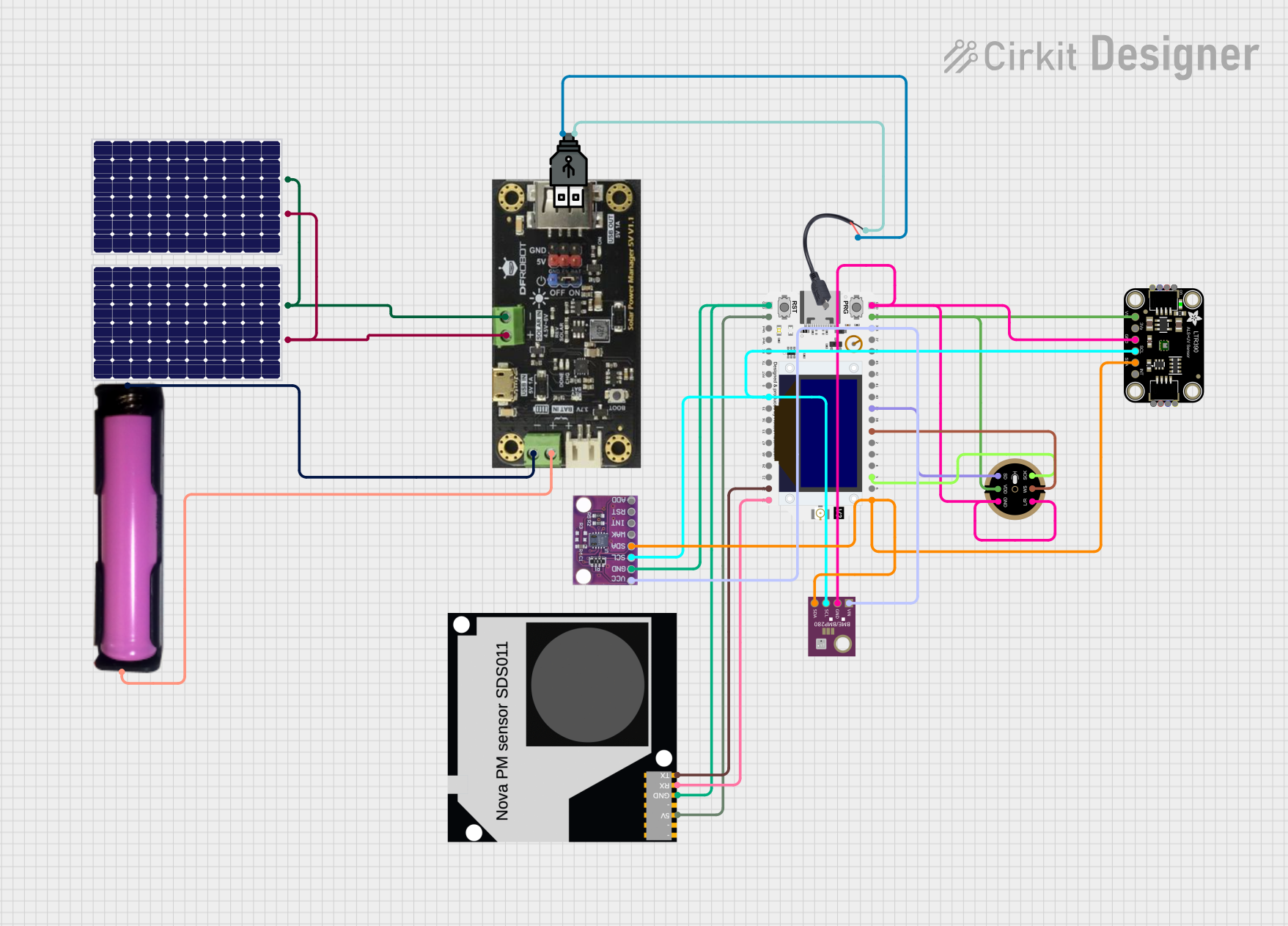
This document provides a detailed overview of a circuit designed to collect environmental data using various sensors and transmit the data via a LoRa module. The circuit includes a microphone, UV light sensor, air quality sensor, temperature/pressure/humidity sensor, and a solar power management system. The data is processed by a microcontroller and sent over a LoRa network.
Component List
INMP441 FRONT MIC
- Description: Digital MEMS microphone
- Pins: L/R, WS, SCK, SD, VDD, GND
WiFi Lora 32V3
- Description: Microcontroller with WiFi and LoRa capabilities
- Pins: pin 1 to pin 36
CJMCU-811
- Description: Air quality sensor
- Pins: VCC, GND, SCL, WAK, INT, RST, ADD, SDA
BME/BMP280
- Description: Temperature, pressure, and humidity sensor
- Pins: GND, SCL, SDA, VIN
Adafruit LTR390 UV Light Sensor
- Description: UV light sensor
- Pins: VCC, 3.3V, GND, SCL, SDA, INT
Solar Power Manager V5
- Description: Solar power management module
- Pins: Solar -, Solar +, Battery -, Battery +, USB -, USB +
Solar Panel
- Description: Solar panel for power generation
- Pins: +, -
Air Quality Sensor
- Description: Air quality sensor
- Pins: TX, 5V, GND, RX
18650 in Holder
- Description: 18650 battery holder
- Pins: GND, VCC
Micro USB to Cable (2 Pin)
- Description: Micro USB to 2-pin cable
- Pins: Micro USB, +, -
USB Power
- Description: USB power source
- Pins: +, -
Wiring Details
INMP441 FRONT MIC
- L/R: Connected to GND
- WS: Connected to WiFi Lora 32V3 pin 7
- SCK: Connected to WiFi Lora 32V3 pin 3
- SD: Connected to WiFi Lora 32V3 pin 9
- VDD: Connected to WiFi Lora 32V3 pin 17
- GND: Connected to GND
WiFi Lora 32V3
- pin 1: Connected to SDA of Adafruit LTR390 UV Light Sensor, CJMCU-811, BME/BMP280
- pin 3: Connected to SCK of INMP441 FRONT MIC
- pin 7: Connected to WS of INMP441 FRONT MIC
- pin 9: Connected to SD of INMP441 FRONT MIC
- pin 17: Connected to VDD of INMP441 FRONT MIC, VCC of Adafruit LTR390 UV Light Sensor
- pin 18: Connected to GND
- pin 19: Connected to GND of Air Quality Sensor, CJMCU-811
- pin 20: Connected to 5V of Air Quality Sensor
- pin 27: Connected to SCL of Adafruit LTR390 UV Light Sensor, CJMCU-811, BME/BMP280
- pin 36: Connected to RX of Air Quality Sensor
- pin 35: Connected to TX of Air Quality Sensor
CJMCU-811
- VCC: Connected to VIN of BME/BMP280, WiFi Lora 32V3 pin 16
- GND: Connected to GND of Air Quality Sensor, WiFi Lora 32V3 pin 19
- SCL: Connected to SCL of Adafruit LTR390 UV Light Sensor, BME/BMP280, WiFi Lora 32V3 pin 27
- SDA: Connected to SDA of Adafruit LTR390 UV Light Sensor, BME/BMP280, WiFi Lora 32V3 pin 1
BME/BMP280
- GND: Connected to GND
- SCL: Connected to SCL of Adafruit LTR390 UV Light Sensor, CJMCU-811, WiFi Lora 32V3 pin 27
- SDA: Connected to SDA of Adafruit LTR390 UV Light Sensor, CJMCU-811, WiFi Lora 32V3 pin 1
- VIN: Connected to VCC of CJMCU-811, WiFi Lora 32V3 pin 16
Adafruit LTR390 UV Light Sensor
- VCC: Connected to VDD of INMP441 FRONT MIC, WiFi Lora 32V3 pin 17
- GND: Connected to GND
- SCL: Connected to SCL of CJMCU-811, BME/BMP280, WiFi Lora 32V3 pin 27
- SDA: Connected to SDA of CJMCU-811, BME/BMP280, WiFi Lora 32V3 pin 1
Solar Power Manager V5
- Solar -: Connected to - of both Solar Panels
- Solar +: Connected to + of both Solar Panels
- Battery -: Connected to GND of 18650 in Holder
- Battery +: Connected to VCC of 18650 in Holder
Solar Panel
- -: Connected to Solar - of Solar Power Manager V5
- +: Connected to Solar + of Solar Power Manager V5
Air Quality Sensor
- RX: Connected to WiFi Lora 32V3 pin 36
- TX: Connected to WiFi Lora 32V3 pin 35
- 5V: Connected to WiFi Lora 32V3 pin 20
- GND: Connected to GND of CJMCU-811, WiFi Lora 32V3 pin 19
18650 in Holder
- GND: Connected to Battery - of Solar Power Manager V5
- VCC: Connected to Battery + of Solar Power Manager V5
Micro USB to Cable (2 Pin)
- +: Connected to + of USB Power
- -: Connected to - of USB Power
USB Power
- +: Connected to + of Micro USB to Cable (2 Pin)
- -: Connected to - of Micro USB to Cable (2 Pin)
Code Documentation
Main Code
import time
from machine import Pin, SoftI2C, SoftSPI, I2S
from lib import ssd1306, sx127x
import bme280
import ltr390
import ccs811
import network
import array
import math

# --- LoRa Sender Konfiguration ---
device_config = {
    'miso': 19,
    'mosi': 27,
    'ss': 18,
    'sck': 5,
    'dio_0': 26,
    'reset': 14,
    'led': 25,
}

lora_params = {
    'frequency': 86965E4,
    'tx_power_level': 14,
    'signal_bandwidth': 125E3,
    'spreading_factor': 8,
    'coding_rate': 5,
    'preamble_length': 8,
    'implicit_header': False,
    'sync_word': 0x12,
    'enable_CRC': False,
    'invert_IQ': False,
}

device_spi = SoftSPI(
    baudrate=10000000,
    polarity=0, phase=0, bits=8, firstbit=SoftSPI.MSB,
    sck=Pin(device_config['sck'], Pin.OUT, Pin.PULL_DOWN),
    mosi=Pin(device_config['mosi'], Pin.OUT, Pin.PULL_UP),
    miso=Pin(device_config['miso'], Pin.IN, Pin.PULL_UP)
)

lora = sx127x.SX127x(device_spi, pins=device_config, parameters=lora_params)

# --- Sensor Konfiguration ---
i2c = SoftI2C(scl=Pin(22), sda=Pin(21))

bme = bme280.BME280(i2c=i2c)
ltr = ltr390.LTR390(i2c)
ccs = ccs811.CCS811(i2c)

# --- Mikrofon I2S Konfiguration ---
mic_sck_pin = Pin(12)
mic_ws_pin = Pin(25)
mic_sd_pin = Pin(32)

audio_in = I2S(
    0,
    sck=mic_sck_pin,
    ws=mic_ws_pin,
    sd=mic_sd_pin,
    mode=I2S.RX,
    bits