
Solar-Powered Smart Home Energy System with Automated Control and Power Inversion
View and Edit Project In Cirkit Designer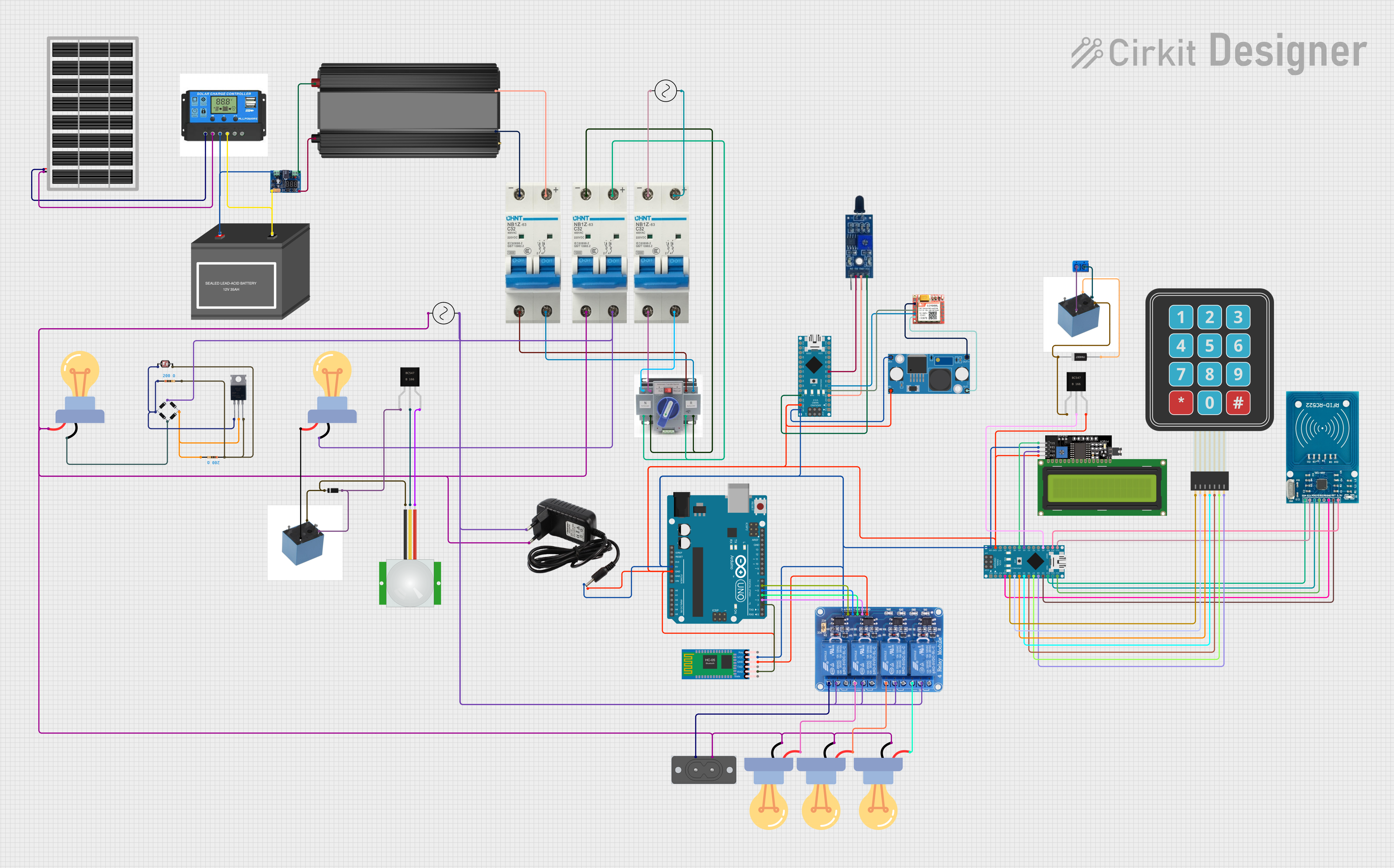
Circuit Documentation
Summary
This document provides a comprehensive overview of a solar-powered circuit with various components including a solar panel, charge controller, low voltage disconnect (LVD), power inverter, battery, circuit breakers, AC supply, automatic transfer switch (ATS), bridge rectifier, LED bulbs, resistors, photocell (LDR), triac (BT139 600), relay modules, transistors (bc547), diodes, sensors (PIR, flame), microcontrollers (Arduino UNO, Arduino Nano), communication modules (HC-05 Bluetooth, sim 800l), power modules (LM2596 Step Down), RFID reader, keypad, and display units. The circuit is designed to manage solar energy for charging a battery and converting it to AC power, with provisions for automatic switching and control via microcontrollers.
Component List
Power Components
- Solar Panel: Converts sunlight into electrical energy.
- Charge Controller: Manages the charging of the battery from the solar panel.
- 12V Battery (mini): Stores electrical energy for later use.
- Power Inverter: Converts DC power from the battery to AC power.
- LVD (Low Voltage Disconnect): Protects the battery from being over-discharged.
- Circuit Breakers: Provide overcurrent protection for the circuit.
- Ac Supply: Provides AC power to the circuit.
- ATS (Automatic Transfer Switch): Switches between solar power and AC supply.
- Bridge Rectifier: Converts AC to DC power.
- LM2596 Step Down Module: Steps down voltage to a lower level.
Control Components
- Arduino UNO: Microcontroller board for controlling various functions.
- Arduino Nano: Compact microcontroller board for embedded control.
- HC-05 Bluetooth Module: Enables wireless communication.
- Relay 4 Channel 5v: Controls high power devices with low power signals.
- Relay 5-pin: Electromechanical switch controlled by an electronic signal.
- sim 800l: GSM/GPRS communication module.
Sensing and Interaction Components
- PIR sensor: Detects motion by sensing changes in infrared levels.
- Flame Sensor: Detects the presence of fire or flame.
- RFID-RC522: RFID reader for contactless communication.
- Membrane Matrix Keypad: Provides user input to the microcontroller.
- Photocell (LDR): Light-dependent resistor, changes resistance with light levels.
Output Components
- LED bulb AC / Bombillo AC: Light-emitting diode bulbs for illumination.
- LCD Display 16x4 I2C: Displays information to the user.
Passive Components
- Resistor: Limits the flow of electric current.
- Diode: Allows current to flow in one direction only.
- 1N4007 Rectifier Diode: Prevents reverse current flow.
- Terminal PCB 2 Pin: Connects wires to the circuit board.
Switching Components
- BT139 600: Triac for controlling AC power.
- bc547: NPN transistor for signal amplification and switching.
Wiring Details
Power Components Wiring
- Solar Panel
gndto Charge ControllerSolar Negativevccto Charge ControllerSolar Positive
- Charge Controller
Battery Positiveto LVDVIN+and 12V Battery+Battery Negativeto LVDVIN-and 12V Battery-
- Power Inverter
+to LVDVOUT+and Circuit Breaker+-to LVDVOUT-and Circuit Breaker-
- LVD
VIN+from Charge ControllerBattery PositiveVIN-from Charge ControllerBattery NegativeVOUT+to Power Inverter+VOUT-to Power Inverter-
- Circuit Breakers
- Multiple connections to ATS, Ac Supply, and Power Inverter for protection.
- Ac Supply
+veto Bridge RectifierSource_in-and Circuit Breaker+-veto Circuit Breaker-
- ATS
+and-connected to Circuit Breakers for automatic switching.
- Bridge Rectifier
Source_in-andsource_in+from Ac Supplysource_out-andsource_out+to various components for DC output.
Control Components Wiring
- Arduino UNO
5VandGNDto various components for power.- Digital pins
D2toD6connected to Relay 4 Channel 5v inputs.
- Arduino Nano
VINandGNDto various components for power.- Digital and analog pins connected to Flame Sensor, sim 800l, RFID-RC522, Membrane Matrix Keypad, and LCD Display.
- HC-05 Bluetooth Module
VCCto power source,GNDto ground.TXDandRXDfor serial communication with Arduino UNO.
Sensing and Interaction Components Wiring
- PIR sensor
VDDandGNDfor power.SIGto bc547basefor signal output.
- Flame Sensor
VCCandGNDfor power.D0to Arduino NanoD6for digital signal output.
- RFID-RC522
VCC (3.3V)andGNDfor power.- SPI pins connected to Arduino Nano for communication.
- Membrane Matrix Keypad
- Rows and columns connected to Arduino Nano digital pins for user input.
- Photocell (LDR)
- Connected in series with resistors and BT139 600 for light sensing.
Output Components Wiring
- LED bulb AC / Bombillo AC
- Multiple connections to Relay 4 Channel 5v
NOterminals and AC power lines.
- Multiple connections to Relay 4 Channel 5v
- LCD Display 16x4 I2C
SDAandSCLto Arduino Nano for I2C communication.VCCandGNDfor power.
Passive Components Wiring
- Resistor
- Connected in series with Photocell (LDR) and BT139 600.
- Diode
anodeto bc547collector,cathodeto Relay 5-pinCoilfor flyback protection.
Switching Components Wiring
- BT139 600
MT1andMT2connected to Bridge rectifier outputs.GATEconnected to resistors and Photocell (LDR).
- bc547
collectorto Relay 5-pinCoiland diodeanode.baseto PIR sensorSIGand Arduino NanoA0.Emitterto ground and PIR sensorVDD.
Documented Code
Arduino UNO Code (Instance ID: 26015be7-91e8-4942-ad0c-174156c2b8b6)
void setup() {
  // put your setup code here, to run once:

}

void loop() {
  // put your main code here, to run repeatedly:

}
Arduino Nano Code (Instance ID: 1ee9ae51-62cd-4ed2-a7a0-5198da9e590d)
void setup() {
  // put your setup code here, to run once:

}

void loop() {
  // put your main code here, to run repeatedly:

}
Arduino Nano Code (Instance ID: b1c2330d-7f25-4753-bcd3-02175bfb05cb)
void setup() {
  // put your setup code here, to run once:

}

void loop() {
  // put your main code here, to run repeatedly:

}
(Note: The actual functionality within the setup() and loop() functions is not provided in the input code and should be implemented according to the specific requirements of the circuit.)