Arduino UNO Controlled Alcohol Detection System with GPS Tracking and Motor Management
Circuit Documentation
Summary
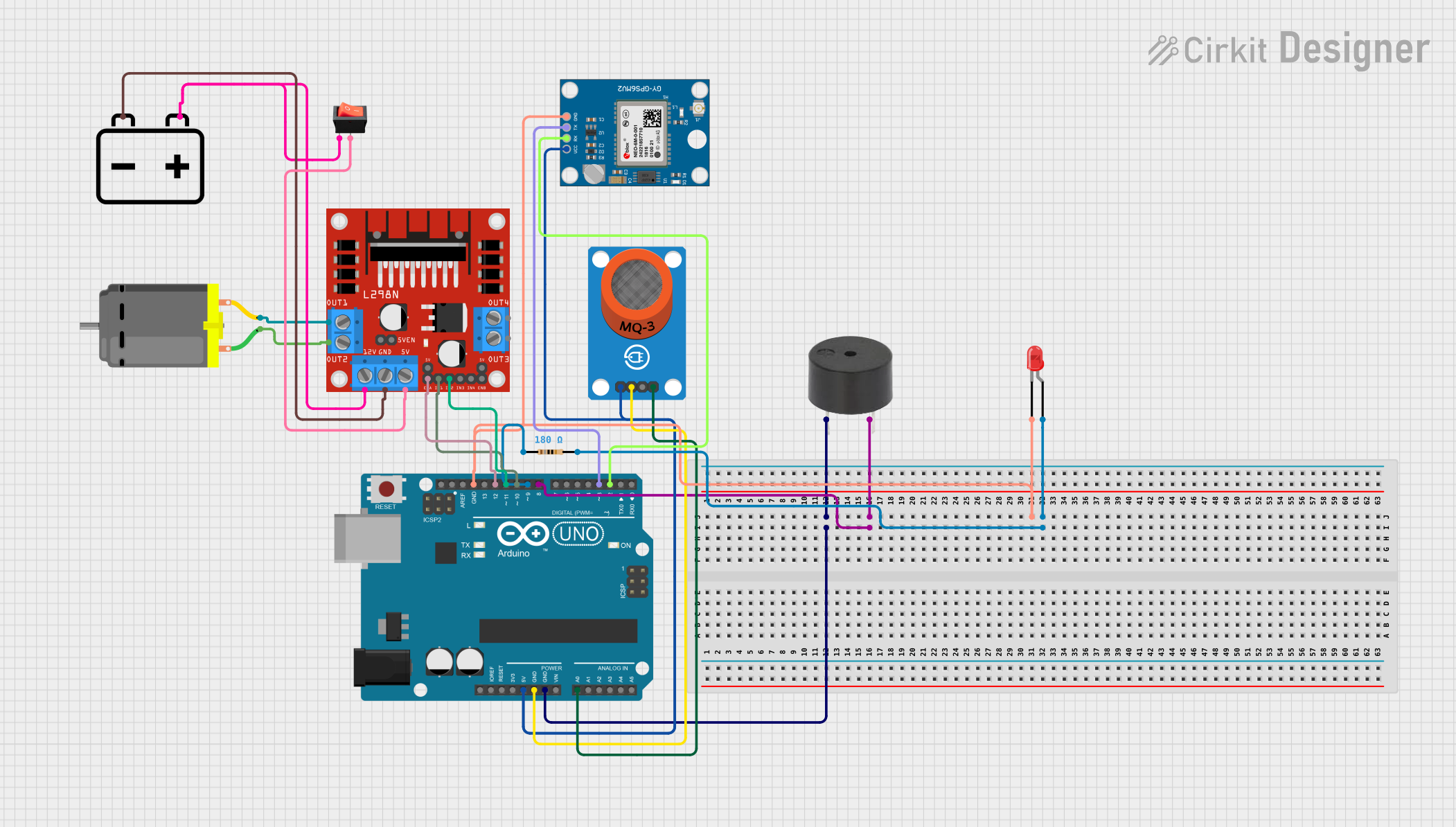
This circuit integrates various components including an Arduino UNO, an MQ-3 alcohol sensor breakout, a buzzer, a red LED with a resistor, three L298N DC motor drivers, a DC motor, a 12V battery, a rocker switch, and a Neo 6M GPS Module. The Arduino UNO serves as the central microcontroller unit, interfacing with the GPS module for location data, controlling the motor driver for motor operations, reading analog values from the MQ-3 sensor, and managing the LED and buzzer for indication purposes. The circuit is powered by a 12V battery, with voltage regulation provided by the Arduino and motor drivers.
Component List
Arduino UNO
- Microcontroller board based on the ATmega328P
- Provides digital and analog I/O pins
- Includes power supply pins and a reset button
MQ-3 Breakout
- Alcohol sensor module
- Outputs both analog and digital signals
Buzzer
- Simple audio signaling device
LED: Two Pin (red)
- Basic red LED for indication
Resistor (180 Ohms)
- Limits current to the LED
L298N DC Motor Driver (x3)
- H-Bridge motor driver
- Capable of driving a pair of DC motors
DC Motor
- Basic DC motor for motion applications
12V Battery
- Provides power to the circuit
Rocker Switch
- Mechanical switch to control power flow
Neo 6M GPS Module
- GPS receiver module for location tracking
Wiring Details
Arduino UNO
5Vconnected to MQ-3 VCC and Neo 6M GPS Module VCCGNDconnected to MQ-3 GND, buzzer GND, LED cathode (through resistor), and Neo 6M GPS Module GNDA0connected to MQ-3 AOD12connected to L298N DC motor driver ENAD11connected to L298N DC motor driver IN2D10connected to L298N DC motor driver IN1D9connected to one side of the resistorD8connected to buzzer PIND3connected to Neo 6M GPS Module TXD2connected to Neo 6M GPS Module RX
MQ-3 Breakout
VCCconnected to Arduino UNO 5VGNDconnected to Arduino UNO GNDAOconnected to Arduino UNO A0
Buzzer
PINconnected to Arduino UNO GNDGNDconnected to Arduino UNO D8
LED: Two Pin (red)
cathodeconnected to Arduino UNO GND (through resistor)anodeconnected to one side of the resistor
Resistor (180 Ohms)
pin1connected to Arduino UNO D9pin2connected to LED anode
L298N DC Motor Driver
ENAconnected to Arduino UNO D12IN2connected to Arduino UNO D11IN1connected to Arduino UNO D10OUT1andOUT2connected to DC Motor pinsGNDconnected to 12V Battery -5Vconnected to rocker switch output12Vconnected to 12V Battery + (through rocker switch)
DC Motor
pin 1connected to L298N DC motor driver OUT2pin 2connected to L298N DC motor driver OUT1
12V Battery
-connected to L298N DC motor driver GND+connected to L298N DC motor driver 12V (through rocker switch)
Rocker Switch
outputconnected to L298N DC motor driver 5Vinputconnected to 12V Battery +
Neo 6M GPS Module
GNDconnected to Arduino UNO GNDTXconnected to Arduino UNO D3RXconnected to Arduino UNO D2VCCconnected to Arduino UNO 5V
Documented Code
Arduino UNO Code (sketch.ino)
void setup() {
  // put your setup code here, to run once:

}

void loop() {
  // put your main code here, to run repeatedly:

}
Note: The provided code is a template and does not contain any functional code. It is expected that the user will add the necessary code to interact with the connected components.