
ESP8266 and INA219-Based Current Spike Detector with Buzzer and Door Reset
View and Edit Project In Cirkit Designer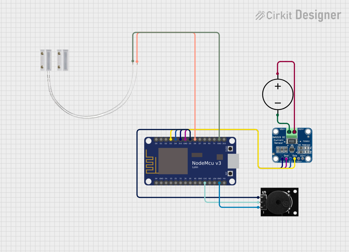
Circuit Documentation
Summary
This circuit is designed to interface with an INA219 current sensor and a NodeMCU V3 ESP8266 microcontroller. The circuit measures current spikes above 500mA. If 10 such spikes are detected, a buzzer is triggered. The system resets when a door switch is opened.
Component List
NodeMCU V3 ESP8266
- Description: A microcontroller based on the ESP8266 Wi-Fi module.
- Pins: A0, GND, VU, S3, S2, S1, SC, S0, SK, 3V3, EN, RST, Vin, D0, D1, D2, D3, D4, D5, D6, D7, D8, RX, TX
INA219
- Description: A current sensor that measures the current, voltage, and power.
- Pins: VCC, GND, SCL, SDA, VIN -, VIN +
DC Power Source
- Description: Provides the necessary power for the circuit.
- Pins: Ground, Positive
Passive Buzzer
- Description: A buzzer that produces sound when activated.
- Pins: S output signal, +VCC, GND
Door MC-38
- Description: A magnetic door switch used to detect the opening of a door.
- Pins: S, GND
Wiring Details
NodeMCU V3 ESP8266
- 3V3 connected to +VCC of Passive Buzzer
- 3V3 connected to VCC of INA219
- GND connected to GND of Passive Buzzer
- GND connected to GND of INA219
- GND connected to GND of Door MC-38
- D3 connected to SDA of INA219
- D4 connected to SCL of INA219
- D5 connected to S output signal of Passive Buzzer
- D6 connected to S of Door MC-38
INA219
- VCC connected to 3V3 of NodeMCU V3 ESP8266
- GND connected to GND of NodeMCU V3 ESP8266
- SCL connected to D4 of NodeMCU V3 ESP8266
- SDA connected to D3 of NodeMCU V3 ESP8266
- VIN - connected to Ground of DC Power Source
- VIN + connected to Positive of DC Power Source
DC Power Source
- Ground connected to VIN - of INA219
- Positive connected to VIN + of INA219
Passive Buzzer
- +VCC connected to 3V3 of NodeMCU V3 ESP8266
- GND connected to GND of NodeMCU V3 ESP8266
- S output signal connected to D5 of NodeMCU V3 ESP8266
Door MC-38
- S connected to D6 of NodeMCU V3 ESP8266
- GND connected to GND of NodeMCU V3 ESP8266
Code Documentation
/*
 * This Arduino Sketch is designed to interface with an INA219 current sensor
 * and a NodeMCU V3 ESP8266 microcontroller. The circuit measures current
 * spikes above 500mA. If 10 such spikes are detected, a buzzer is triggered.
 * The system resets when a door switch is opened.
 */

#include <Wire.h>
#include <Adafruit_INA219.h>

Adafruit_INA219 ina219;

const int buzzerPin = D5; // Pin connected to the buzzer
const int doorSwitchPin = D6; // Pin connected to the door switch

int spikeCount = 0;
const int maxSpikes = 10;
const float currentThreshold = 0.5; // 500mA

const int debounceDelay = 50; // 50 milliseconds debounce delay
unsigned long lastDebounceTime = 0;
int lastDoorSwitchState = HIGH;
bool spikeDetected = false;

unsigned long buzzerOnTime = 0;
const unsigned long buzzerDuration = 500; // 500 milliseconds
bool buzzerState = false;

void setup() {
  Serial.begin(115200);
  Wire.begin(); // Remove explicit pin arguments
  ina219.begin();
  pinMode(buzzerPin, OUTPUT);
  pinMode(doorSwitchPin, INPUT_PULLUP);
  digitalWrite(buzzerPin, LOW);
}

void loop() {
  float current_mA = ina219.getCurrent_mA();
  Serial.print("Current: ");
  Serial.print(current_mA);
  Serial.println(" mA");

  if (current_mA > currentThreshold * 1000 && !spikeDetected) {
    spikeCount++;
    spikeDetected = true;
    Serial.print("Spike count: ");
    Serial.println(spikeCount);
  } else if (current_mA <= currentThreshold * 1000) {
    spikeDetected = false;
  }

  if (spikeCount >= maxSpikes) {
    if (!buzzerState) {
      buzzerState = true;
      buzzerOnTime = millis();
      digitalWrite(buzzerPin, HIGH); // Turn on buzzer
    } else if (millis() - buzzerOnTime >= buzzerDuration) {
      buzzerState = false;
      digitalWrite(buzzerPin, LOW); // Turn off buzzer
    }
  }

  int doorSwitchState = digitalRead(doorSwitchPin);
  if (doorSwitchState != lastDoorSwitchState) {
    lastDebounceTime = millis();
  }

  if ((millis() - lastDebounceTime) > debounceDelay) {
    if (doorSwitchState == LOW) {
      spikeCount = 0;
      digitalWrite(buzzerPin, LOW); // Reset buzzer
      Serial.println("System reset.");
    }
  }

  lastDoorSwitchState = doorSwitchState;

  // Use non-blocking delay
  static unsigned long lastLoopTime = 0;
  if (millis() - lastLoopTime >= 1000) {
    lastLoopTime = millis();
  }
}
This code interfaces with the INA219 current sensor and the NodeMCU V3 ESP8266 microcontroller. It measures current spikes above 500mA and triggers a buzzer if 10 such spikes are detected. The system resets when a door switch is opened.