
Arduino 101 and HC-05 Bluetooth Controlled Multi-IR Sensor and LED System
View and Edit Project In Cirkit Designer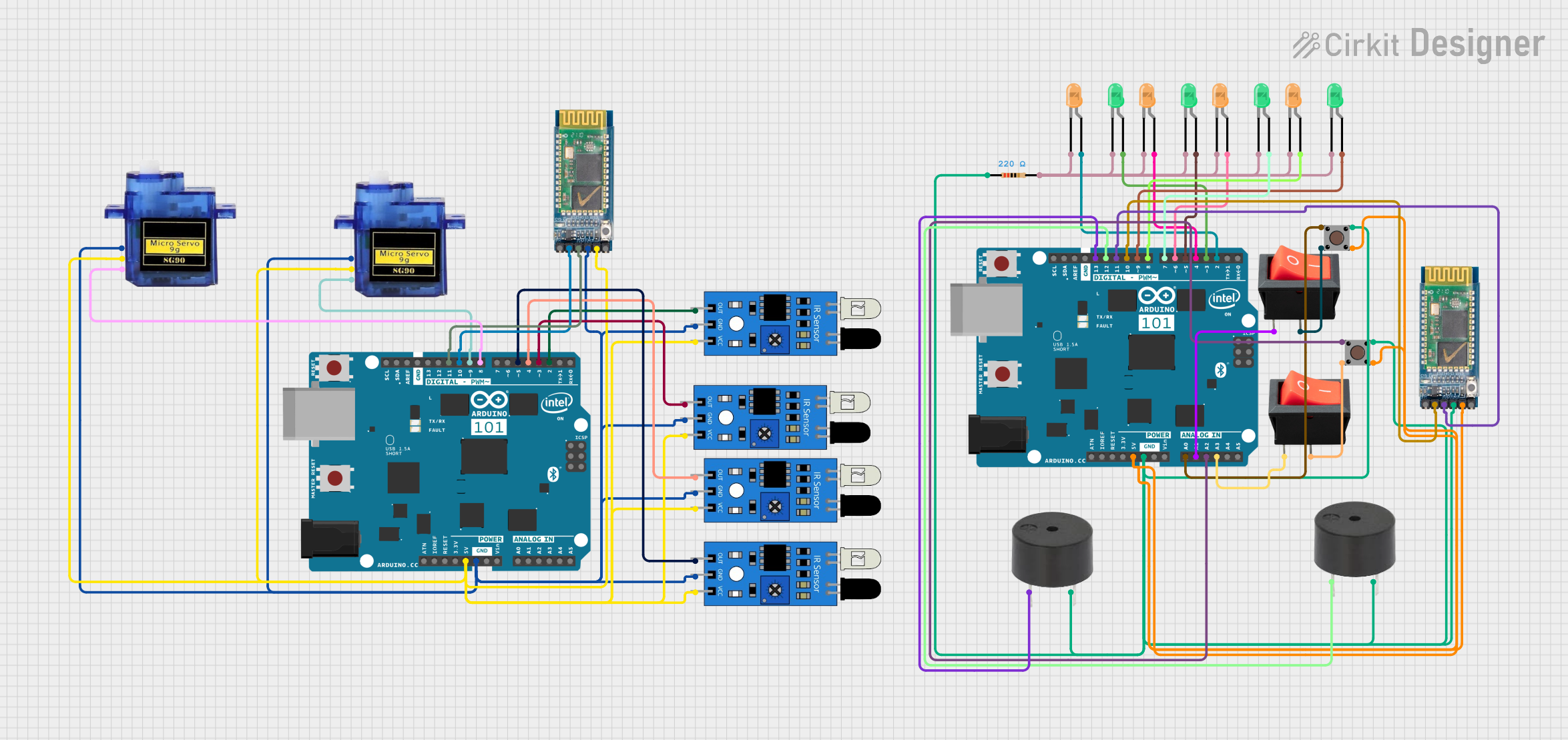
Circuit Documentation
Summary
This circuit involves multiple IR sensors, an Arduino 101 microcontroller, a Bluetooth module (HC-05), micro servos, LEDs, pushbuttons, a rocker switch, and buzzers. The circuit is designed to detect IR signals, control LEDs and servos, and communicate via Bluetooth. The Arduino 101 microcontroller is the central unit that processes inputs from the IR sensors and pushbuttons and controls the outputs to the LEDs, servos, and buzzers.
Component List
IR Sensor
- Pins: out, gnd, vcc
- Description: Infrared sensor used for detecting IR signals.
Arduino 101
- Pins: A5/SCL, A4/SDA, AREF, GND, D13/SCK, D12/MISO, D11 PWM/MOSI, D10 PWM/SS, D9 PWM, D8, D7, D6 PWM, D5 PWM, D4, D3 PWM, D2, D1/TX, D0/RX, AIN, ioref, RESET, 3V3, 5V, VIN, A0, A1, A2, A3, ICSP MISO, ICSP SCK, ICSP MOSI
- Description: Microcontroller used for processing inputs and controlling outputs.
Micro Servo 9G
- Pins: GND, +5V, PWM
- Description: Small servo motor used for precise control of angular position.
HC-05
- Pins: STATE, RXD, TXD, GND, VCC, EN
- Description: Bluetooth module used for wireless communication.
LED: Two Pin (orange)
- Pins: cathode, anode
- Description: Orange LED used for visual indication.
LED: Two Pin (green)
- Pins: cathode, anode
- Description: Green LED used for visual indication.
Resistor
- Pins: pin1, pin2
- Description: Resistor with a resistance of 220 Ohms.
Pushbutton
- Pins: Pin 3 (out), Pin 4 (out), Pin 1 (in), Pin 2 (in)
- Description: Pushbutton used for user input.
Rocker Switch
- Pins: output, input
- Description: Rocker switch used for toggling states.
Buzzer
- Pins: PIN, GND
- Description: Buzzer used for sound output.
Wiring Details
IR Sensor
- out connected to D3 PWM on Arduino 101
- gnd connected to common ground
- vcc connected to common 5V
IR Sensor
- out connected to D2 on Arduino 101
- gnd connected to common ground
- vcc connected to common 5V
IR Sensor
- out connected to D4 on Arduino 101
- gnd connected to common ground
- vcc connected to common 5V
IR Sensor
- out connected to D5 PWM on Arduino 101
- gnd connected to common ground
- vcc connected to common 5V
Arduino 101
- GND connected to common ground
- 5V connected to common 5V
- D3 PWM connected to out of IR Sensor
- D2 connected to out of IR Sensor
- D4 connected to out of IR Sensor
- D5 PWM connected to out of IR Sensor
- D11 PWM/MOSI connected to TXD of HC-05
- D10 PWM/SS connected to RXD of HC-05
- D9 PWM connected to PWM of Micro Servo 9G
- D8 connected to PWM of Micro Servo 9G
- D13/SCK connected to PIN of Buzzer
- D12/MISO connected to PIN of Buzzer
- A0 connected to Pin 2 (in) of Pushbutton
- A1 connected to input of Rocker Switch
- A2 connected to Pin 2 (in) of Pushbutton
- A3 connected to input of Rocker Switch
Micro Servo 9G
- GND connected to common ground
- +5V connected to common 5V
- PWM connected to D9 PWM on Arduino 101
Micro Servo 9G
- GND connected to common ground
- +5V connected to common 5V
- PWM connected to D8 on Arduino 101
HC-05
- GND connected to common ground
- VCC connected to common 5V
- TXD connected to D11 PWM/MOSI on Arduino 101
- RXD connected to D10 PWM/SS on Arduino 101
LED: Two Pin (orange)
- cathode connected to common ground
- anode connected to D2 on Arduino 101
LED: Two Pin (green)
- cathode connected to common ground
- anode connected to D3 PWM on Arduino 101
LED: Two Pin (orange)
- cathode connected to common ground
- anode connected to D4 on Arduino 101
LED: Two Pin (green)
- cathode connected to common ground
- anode connected to D5 PWM on Arduino 101
LED: Two Pin (orange)
- cathode connected to common ground
- anode connected to D6 PWM on Arduino 101
LED: Two Pin (green)
- cathode connected to common ground
- anode connected to D7 on Arduino 101
LED: Two Pin (orange)
- cathode connected to common ground
- anode connected to D8 on Arduino 101
LED: Two Pin (green)
- cathode connected to common ground
- anode connected to D9 PWM on Arduino 101
Resistor
- pin1 connected to common ground
- pin2 connected to cathode of LEDs
Pushbutton
- Pin 3 (out) connected to VCC of HC-05
- Pin 4 (out) connected to output of Rocker Switch
- Pin 1 (in) connected to common ground
- Pin 2 (in) connected to A0 on Arduino 101
Rocker Switch
- output connected to Pin 4 (out) of Pushbutton
- input connected to A1 on Arduino 101
Buzzer
- PIN connected to D13/SCK on Arduino 101
- GND connected to common ground
Buzzer
- PIN connected to D12/MISO on Arduino 101
- GND connected to common ground
Documented Code
Arduino 101 (Instance 1)
void setup() {
  // put your setup code here, to run once:

}

void loop() {
  // put your main code here, to run repeatedly:

}
Arduino 101 (Instance 2)
#include <SoftwareSerial.h>

SoftwareSerial BT(10, 11); // RX, TX for HC-05

// Define LED pin pairs (OLED and GLED)
const int oledPins[] = {2, 4, 6, 8};  // OLED pins
const int gledPins[] = {3, 5, 7, 9};  // GLED pins
const int numLEDs = 4;

// Define potentiometer pin
const int potPin = A0;  // Potentiometer connected to analog pin A0

void setup() {
  Serial.begin(9600);  // Serial Monitor communication
  BT.begin(38400);     // Bluetooth module baud rate

  // Initialize all pins as OUTPUT
  for (int i = 0; i < numLEDs; i++) {
    pinMode(oledPins[i], OUTPUT);
    pinMode(gledPins[i], OUTPUT);
  }

  // Initialize all LEDs to be OFF
  for (int i = 0; i < numLEDs; i++) {
    digitalWrite(oledPins[i], LOW);
    digitalWrite(gledPins[i], LOW);
  }

  Serial.println("Slave ready...");
}

void loop() {
  if (BT.available()) {
    String command = BT.readStringUntil('\n');
    command.trim();  // Remove any extra spaces

    Serial.println("Received: " + command);

    // Match command and control LEDs accordingly
    if (command == "LED1_ON") {