Arduino Mega 2560 Based Load Cell Weight Measurement System with HX711 and LED Indicator
Circuit Documentation
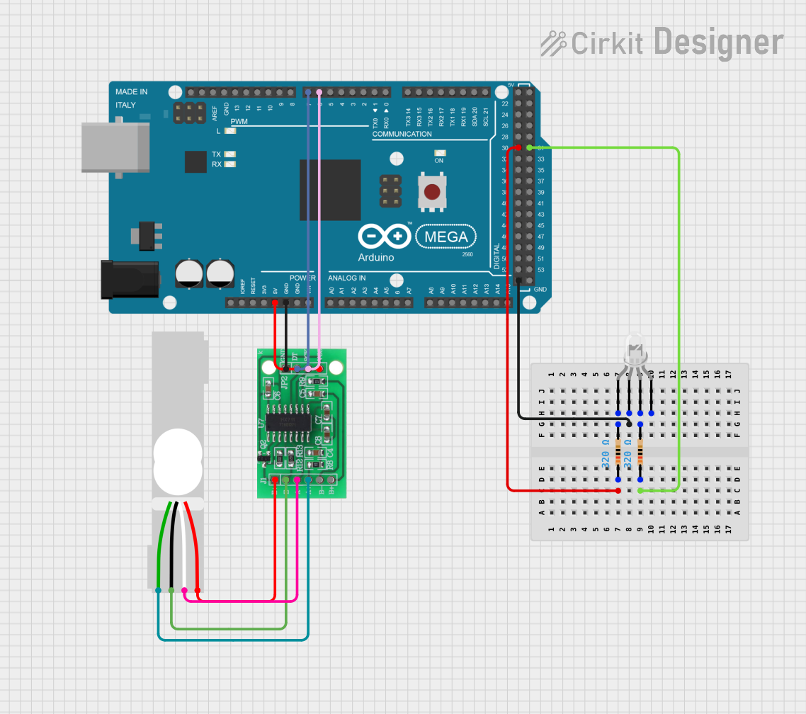
Summary of the Circuit
This circuit is designed around the Arduino Mega 2560 microcontroller, which serves as the central processing unit. The circuit includes a load cell interfaced with an HX711 bridge sensor interface for weight measurement, and a common cathode LED for indication purposes. Two resistors are used to limit the current through the LED. The HX711 is powered by the Arduino and communicates with it using digital pins. The load cell is connected to the HX711, which digitizes the analog signals from the load cell.
Component List
Arduino Mega 2560
- Microcontroller board based on the ATmega2560
- It has 54 digital input/output pins (of which 15 can be used as PWM outputs), 16 analog inputs, 4 UARTs (hardware serial ports), a 16 MHz crystal oscillator, a USB connection, a power jack, an ICSP header, and a reset button.
Load Cell - Red/white/black/green
- A transducer that generates an electrical signal whose magnitude is directly proportional to the force being measured.
- It has four pins: Excitation+ (E+), Excitation- (E-), Signal+ (A+), and Signal- (A-).
HX711 - Bridge Sensor Interface
- A precision 24-bit analog-to-digital converter (ADC) designed for weigh scales and industrial control applications to interface directly with a bridge sensor.
- It has multiple pins for power supply, ground, data output, and clock input, as well as connections for the bridge sensor (load cell).
LED: Four Pin (Common Cathode)
- A light-emitting diode with four pins: one common cathode and three anodes corresponding to the red, green, and blue channels.
- It can be used to indicate various statuses in a circuit by changing the color.
Resistor (320 Ohms)
- A passive two-terminal electrical component that implements electrical resistance as a circuit element.
- In this circuit, two resistors of 320 Ohms are used to limit the current through the LED.
Wiring Details
Arduino Mega 2560
- D30: Connected to one end of a 320 Ohm resistor.
- D31: Connected to one end of another 320 Ohm resistor.
- GND: Connected to the common cathode of the LED.
- 5V: Provides power to the HX711.
- D6 PWM: Connected to the SCK - CLOCK (IN) pin of the HX711.
- D7 PWM: Connected to the DATA (OUT) pin of the HX711.
Load Cell - Red/white/black/green
- E+: Connected to E+ of the HX711.
- A-: Connected to A- of the HX711.
- E-: Connected to E- of the HX711.
- A+: Connected to A+ of the HX711.
HX711 - Bridge Sensor Interface
- 3.3/3.5V Supply: Powered by the 5V pin from the Arduino Mega 2560.
- GND - GROUND: Connected to the GND pin on the Arduino Mega 2560.
- SCK - CLOCK (IN): Receives clock signals from D6 PWM on the Arduino Mega 2560.
- DATA (OUT): Sends data to D7 PWM on the Arduino Mega 2560.
- E+, A-, E-, A+: Interfaced with the corresponding pins on the Load Cell.
LED: Four Pin (Common Cathode)
- Common Cathode: Connected to GND on the Arduino Mega 2560.
- Red Anode: Connected to the other end of the 320 Ohm resistor linked to D30 on the Arduino Mega 2560.
- Green Anode: Connected to the other end of the 320 Ohm resistor linked to D31 on the Arduino Mega 2560.
Resistor (320 Ohms)
- One resistor is connected between D30 on the Arduino Mega 2560 and the red anode of the LED.
- The other resistor is connected between D31 on the Arduino Mega 2560 and the green anode of the LED.
Documented Code
Arduino Mega 2560 - sketch.ino
void setup() {
  // put your setup code here, to run once:

}

void loop() {
  // put your main code here, to run repeatedly:

}
Arduino Mega 2560 - documentation.txt
(No additional documentation provided for the code)
This concludes the documentation for the given circuit. The circuit is designed for basic interfacing and does not include complex functionalities in the provided code. Further development of the code is required to utilize the full capabilities of the components.