Arduino UNO Controlled Relay Module with I2C LCD Display
Circuit Documentation
Summary
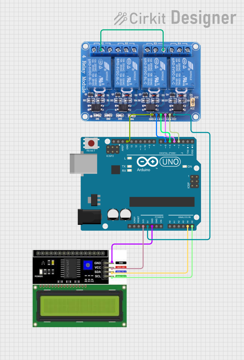
This circuit consists of an Arduino UNO microcontroller, an LCD I2C Display, and a 4-channel relay module. The Arduino UNO controls the relays and communicates with the LCD display via the I2C protocol. The LCD displays a welcome message and the frequency of a square wave generated on one of the relay control pins. The relays can be controlled via digital pins D3, D4, D5, and D6 on the Arduino.
Component List
Arduino UNO
- Description: A microcontroller board based on the ATmega328P.
- Pins: UNUSED, IOREF, Reset, 3.3V, 5V, GND, Vin, A0, A1, A2, A3, A4, A5, SCL, SDA, AREF, D13, D12, D11, D10, D9, D8, D7, D6, D5, D4, D3, D2, D1, D0
LCD I2C Display
- Description: A 16x2 character LCD display with I2C interface.
- Pins: GND, VCC, SDA, SCL
Relay 4 Channel 5v
- Description: A 4-channel relay module that can be controlled by a 5V signal.
- Pins: GND, IN1, IN2, IN3, IN4, VCC, COM1, COM2, COM3, COM4, NO1, NO2, NO3, NO4, NC1, NC2, NC3, NC4
Wiring Details
Arduino UNO
GND is connected to:
- GND of LCD I2C Display
- GND of Relay 4 Channel 5v
3.3V is connected to VCC of LCD I2C Display
A4 is connected to SDA of LCD I2C Display
A5 is connected to SCL of LCD I2C Display
D6 is connected to IN1 of Relay 4 Channel 5v
D5 is connected to IN2 of Relay 4 Channel 5v
D4 is connected to IN3 of Relay 4 Channel 5v
D3 is connected to IN4 of Relay 4 Channel 5v
5V is connected to VCC of Relay 4 Channel 5v
LCD I2C Display
GND is connected to GND of Arduino UNO
VCC is connected to 3.3V of Arduino UNO
SDA is connected to A4 of Arduino UNO
SCL is connected to A5 of Arduino UNO
Relay 4 Channel 5v
GND is connected to GND of Arduino UNO
IN1 is connected to D6 of Arduino UNO
IN2 is connected to D5 of Arduino UNO
IN3 is connected to D4 of Arduino UNO
IN4 is connected to D3 of Arduino UNO
VCC is connected to 5V of Arduino UNO
NO3 is connected to COM1 of Relay 4 Channel 5v
Code Documentation
/*
 * This Arduino Sketch initializes an I2C LCD display and controls a 4-channel
 * relay module. The LCD displays a welcome message and then continuously
 * updates to show the frequency of a square wave generated on one of the
 * relay control pins. The relays can be controlled via digital pins D3, D4,
 * D5, and D6.
 */

#include <Wire.h>
#include <LiquidCrystal_I2C.h>

// Initialize the LCD with I2C address 0x27 and 16x2 display
LiquidCrystal_I2C lcd(0x27, 16, 2);

// Relay control pins
const int relay1 = 6;
const int relay2 = 5;
const int relay3 = 4;
const int relay4 = 3;

// Frequency measurement variables
unsigned long previousMillis = 0;
const long interval = 1000; // Interval for frequency calculation (1 second)
int frequency = 0;

void setup() {
  // Initialize the LCD
  lcd.begin(16, 2); // Corrected to include the number of columns and rows
  lcd.backlight();
  lcd.setCursor(0, 0);
  lcd.print("Welcome!");
  lcd.setCursor(0, 1);
  lcd.print("Relay Control");
  delay(2000); // Display welcome message for 2 seconds

  // Set relay pins as outputs
  pinMode(relay1, OUTPUT);
  pinMode(relay2, OUTPUT);
  pinMode(relay3, OUTPUT);
  pinMode(relay4, OUTPUT);

  // Initialize relays to off
  digitalWrite(relay1, LOW);
  digitalWrite(relay2, LOW);
  digitalWrite(relay3, LOW);
  digitalWrite(relay4, LOW);
}

void loop() {
  unsigned long currentMillis = millis();

  // Generate square wave on relay1 pin
  digitalWrite(relay1, HIGH);
  delay(500); // 500ms HIGH
  digitalWrite(relay1, LOW);
  delay(500); // 500ms LOW

  // Calculate frequency every second
  if (currentMillis - previousMillis >= interval) {
    previousMillis = currentMillis;
    frequency = 1; // Frequency is 1 Hz (1 cycle per second)

    // Update LCD with frequency
    lcd.clear();
    lcd.setCursor(0, 0);
    lcd.print("Frequency:");
    lcd.setCursor(0, 1);
    lcd.print(frequency);
    lcd.print(" Hz");
  }
}
This code initializes the LCD display and sets up the relay control pins. In the setup function, the LCD displays a welcome message, and the relay pins are set as outputs and initialized to the off state. The loop function generates a square wave on the first relay pin and updates the LCD with the frequency of the square wave every second.